This thread has been locked.

If you have a related question, please click the "Ask a related question" button in the top right corner. The newly created question will be automatically linked to this question.

TUSB1046A-DCI: Schematic review

Part Number: TUSB1046A-DCI


Hi Sirs,

As discussed before.

We have finish our schematic and have few questions as below.

Could you help check it?
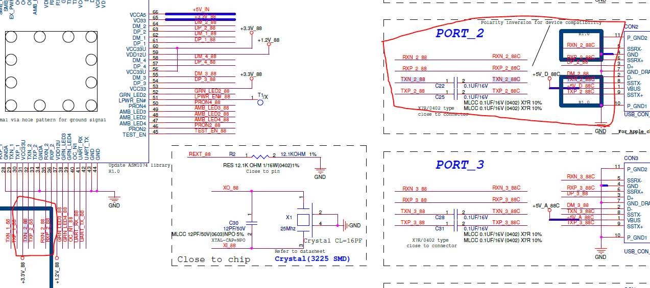
Schematic:

TUSB1046.pdf

1. Is this schematic ok for 5V/3A?

2. Is this schematic ok for 

3. Is there need to connect the SPI interface?

4. What is the handling of HV_GATE1/2 and SENSEP/N if the output of 5V or higher is not supported?
5. Please provide TPS65982ABZQZR UL report
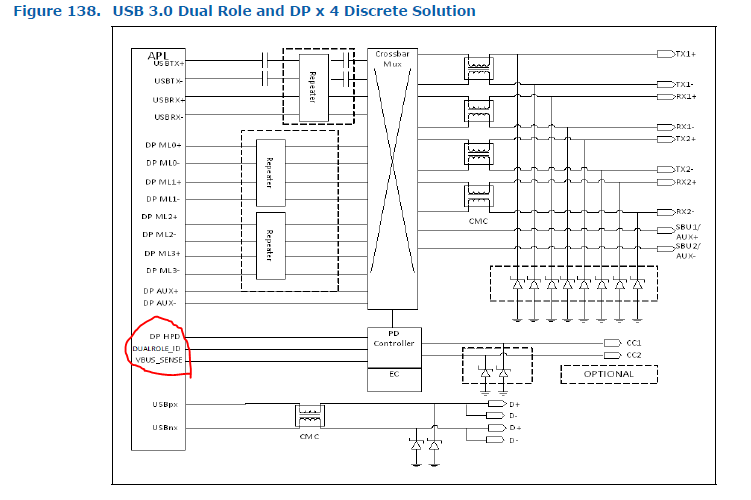
6. When inserting DP, is GPIO4 high action? HPD of APL is low action

Thanks!!

  • Hi,

    The TUSB1046A portion of the schematic can be review by me. Please find my notes below.

    • SSRX path from connector to TUSB1046A should have 330 nF and SSTX should have 220 nF.
    • I2C_EN should be pulled down with 1k resistor for GPIO mode
    • 2M pull down on SBU recommended
    • HPDIN pins are inputs and should be associated with DP enable signal or HPD from connector.

    After the TUSB1046A review and questions, I will loop in the team that supports TPS65982A to help answer your questions above. Please let me know.

  • Hi Sirs,

    Thanks for your reply.

    Please refer red word

    • Does EQ and DPEQ and SSEQ reserve pu high/low resistance, no need for the last piece?

    We will receive the TUSB1046A through the ASM1074 U3 HUB.

    According to the DEMO circuit provided by ASM

    Output only TX string 0.1uF to connector
    So if you receive ASM1074 is it
    ASM1074 TX -> 0.1U > TUSB1046 TX
    ASM1074 RX -> 0.1U > TUSB1046 RX


    • I2C_EN should be pulled down with 1k resistor for GPIO mode

    OR829 has been uploaded

    • 2M pull down on SBU recommended

    Changed 2M and uploaded
    I don't see 2M pu low resistance in the demo circuit?


    Does EQ and DPEQ and SSEQ reserve pu high/low resistance, no need for the last piece?


  • Hi,

    The schematic seems correct for the 5V/3A around the PD controller. This device requires the SPI interface. To obtain the  TPS65982ABZQZR UL report you must contact UL. Yes, GPIO4 will be high action.

  • Hi Sirs,

    Sorry for pushed.

    Have any update on here?

    Changed 2M and uploaded
    I don't see 2M pu low resistance in the demo circuit?


    Does EQ and DPEQ and SSEQ reserve pu high/low resistance, no need for the last piece?

    Thanks!!

  • Hi Sirs,

    Thanks for your reply.

    Still have few questions, please refer as below

    1. Does the USB type C dual role need to be pulled out from the specified USB3 port?

    2. In the intel PDG mentioned that the dualrole ID and VBUS_SENSE should be connected to the PD.
    Please help me to confirm where to receive it?

    3. About this device requires the SPI interface.

    Could you provide ROM file? How to pack into the BIOS?

  • Hi,

    Could you describe the signal path from connector to USB Host? this will impact the AC caps needed. For a USB Hub to USB connector implementation, having only 0.1 uF on SSTX. Adding a redriver can change this and due to USB 3.2 spec changes 0.22 for SSTX and 0.33 uF for SSRX are additional recommended values. 2M pull down resistors are recommended to correctly bias AUX to SBU internal switch. EQ, DPEQ,SSEQ should have reserved pull up and pull down resistances. Please use the values specified in Table 1 in TUSB1046A datasheet to obtain the correct EQ settings.  

  •  Could you support the PD questions above from Shu-Cheng?

  • Hi Sirs,

    Thanks for your reply

    Does this one support U3 dual role?
    Currently known in A86 windows of X86 does not support device mode
    Can it be supported through this 1046?
    If not, is there a corresponding IC?

    Please refer to the attachment as the below for the following questions.
    The current HW line is as follows (this platform only supports USB3.1 GEN I)
    SOC -> TI1046 -> type C connector

    123.pdf

  • Hi,

    I am working on solving all your PD questions. Will have a reply back to all the concerning questions by today. Thanks

  • Hi,

    1- No it does not have to be removed since you can connect two DRP systems together but the data role can be corrected in PD by setting the correct Data Role Swap.

    2- In the case for PDG from intel, you are working with host so your system should data role swap to a DFP when it is initially connected as an UFP. I am uncertain if TUSB1046 supports bi-directional USB3 on SSTX1/SSRX1 (Normal Orientation) If it does, then you can connect those two GPIOs from the PD controller to the PCH tp let the system know when they are connected as an USB device. If I can remember from intel, only a single USB port on the PCH can connect as an USB device and cannot have more than one.

    3- The SPI pins are required to connect the PD controller to the flash where its firmware resides. Without this the part will not do anything. You can generate the required binary that will be stored in the flash by using the tool in the link bellow. http://www.ti.com/tool/tps6598x-config. At power up (Dead Battery or normal operation) the PD controller will read from the flash connected through SPI and load its firmware. The PD controller's binary will not reside in the BIOS.

    You asked initially this question also 4. What is the handling of HV_GATE1/2 and SENSEP/N if the output of 5V or higher is not supported?

    - They will be disable and not driving gate above source.

    Hope this helps. Let us know if this solves your thread. Thanks