This thread has been locked.

If you have a related question, please click the "Ask a related question" button in the top right corner. The newly created question will be automatically linked to this question.

TCAN332G: TCAN332G waveform puzzled

Part Number: TCAN332G
Other Parts Discussed in Thread: TCAN332,

Could you help me about this puzzled.

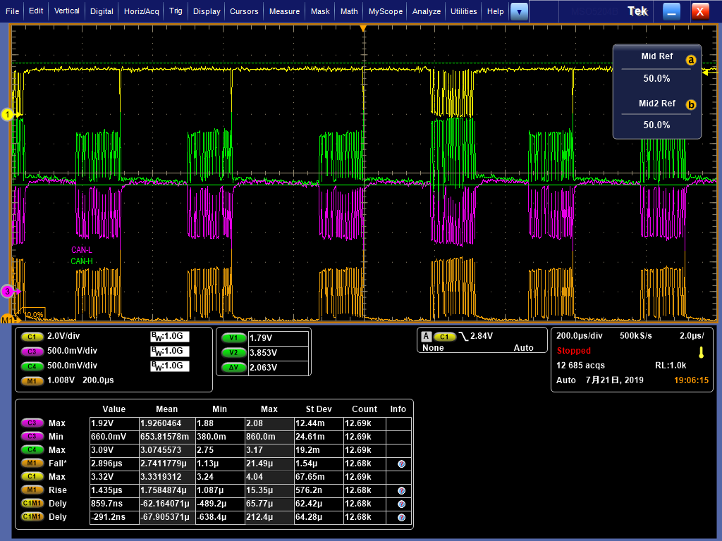
CTM is evaluate TCAN332 and they test the timing value of node after TCAN332G connects to the 100-meter network cable, the rate is 500Kbps.

The measured tpHR (C1M1) was 316 ns, tpLD was 54 ns, tR = 173 ns, and tF = 531 ns. The test waveforms are shown in the attachment. Received has not been tested yet. 

Are these values reasonable?

Problem: There is no limit value in the datasheet 
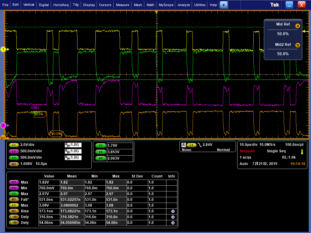
. How to determine whether this measured data meets the chip specifications?                               


  • Seasat,

    Thank you for bringing this to our attention. To answer your question, a delay that large is not typical behavior of this device. If you could share a schematic through email, that would be very helpful. I have a few questions:

    • Are there 5V transceivers on the bus along with 3.3V transceivers? Or is this measurement only taken with the cable attached? The voltage level in the CANH and CANL waveforms looks like the recessive level is shifting significantly.
    • Can zoomed in waveforms showing one dominant to recessive edge, and one recessive to dominant edge be shared? The scope shots that you shared have a lot of information in them, but zoomed in even further would help more. Showing TXD, CANH, CANL, and CANH-CANL is preferred, as you have shared already.

    Once the schematic is available we can shed some more light on this as well. And please let me know if you have any other questions or concerns.

    Regards,

  • Hi Seasat,

    Do you have any updates you can share?  The waveforms you showed previously all look OK and should result in proper communication.  If you were concerned about the variation in the single-ended recessive level that Eric mentioned you could try implementing split termination as shown in Figure 36 of the datasheet.  With respect to timing, the main thing to check would be to ensure the total delay from TXD of node 1 to RXD of node 2 plus the delay of TXD of node 2 to RXD of node 1 is less than ~75% of the time required for a single bit (2 us in this case).  This helps to sure that the arbitration portion of the CAN protocol works successfully.  In this case the total delay should be dominated by the cable delay (typically around 5 ns/m), so if communication issues are encountered you may need to slow down the data rate to get more timing margin.

    Max