This thread has been locked.

If you have a related question, please click the "Ask a related question" button in the top right corner. The newly created question will be automatically linked to this question.

DS8921: DS8921 RS422 Communication Abnormality

Part Number: DS8921

Hi ,

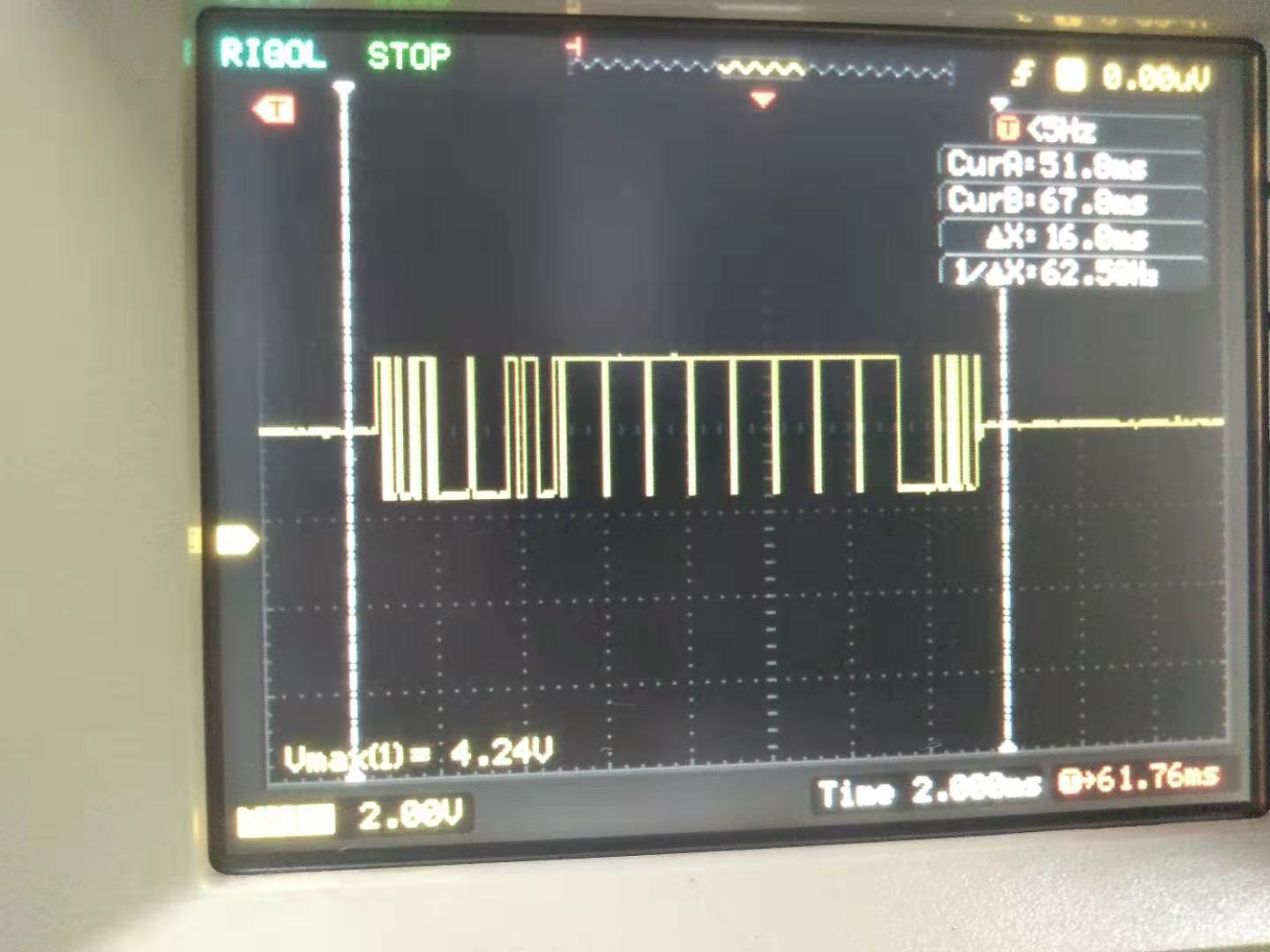
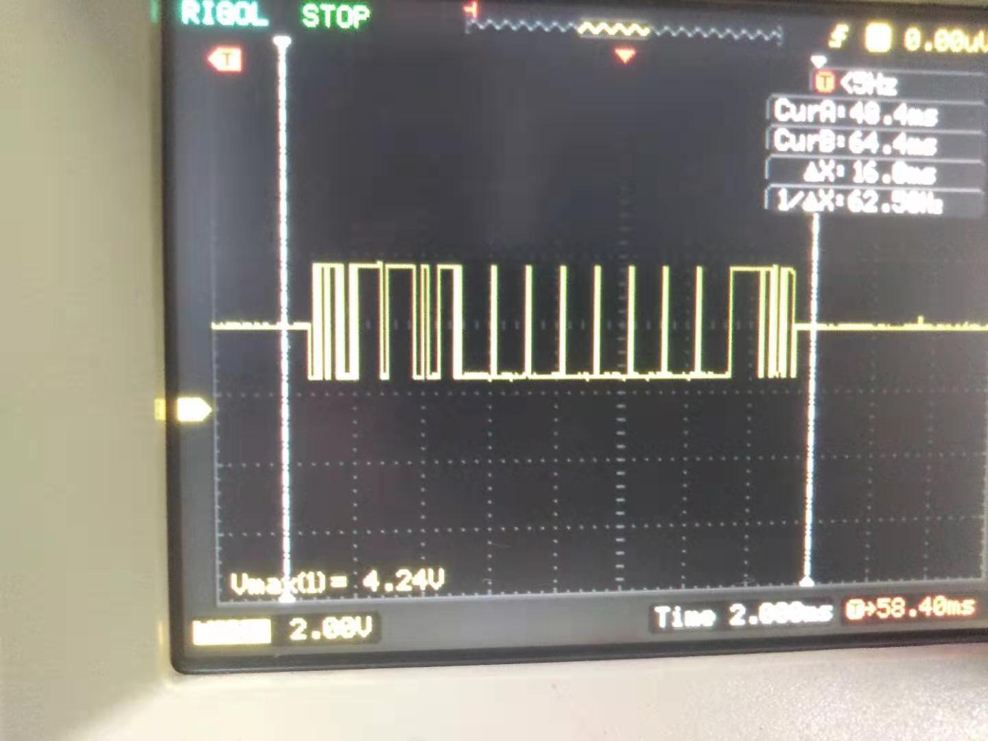
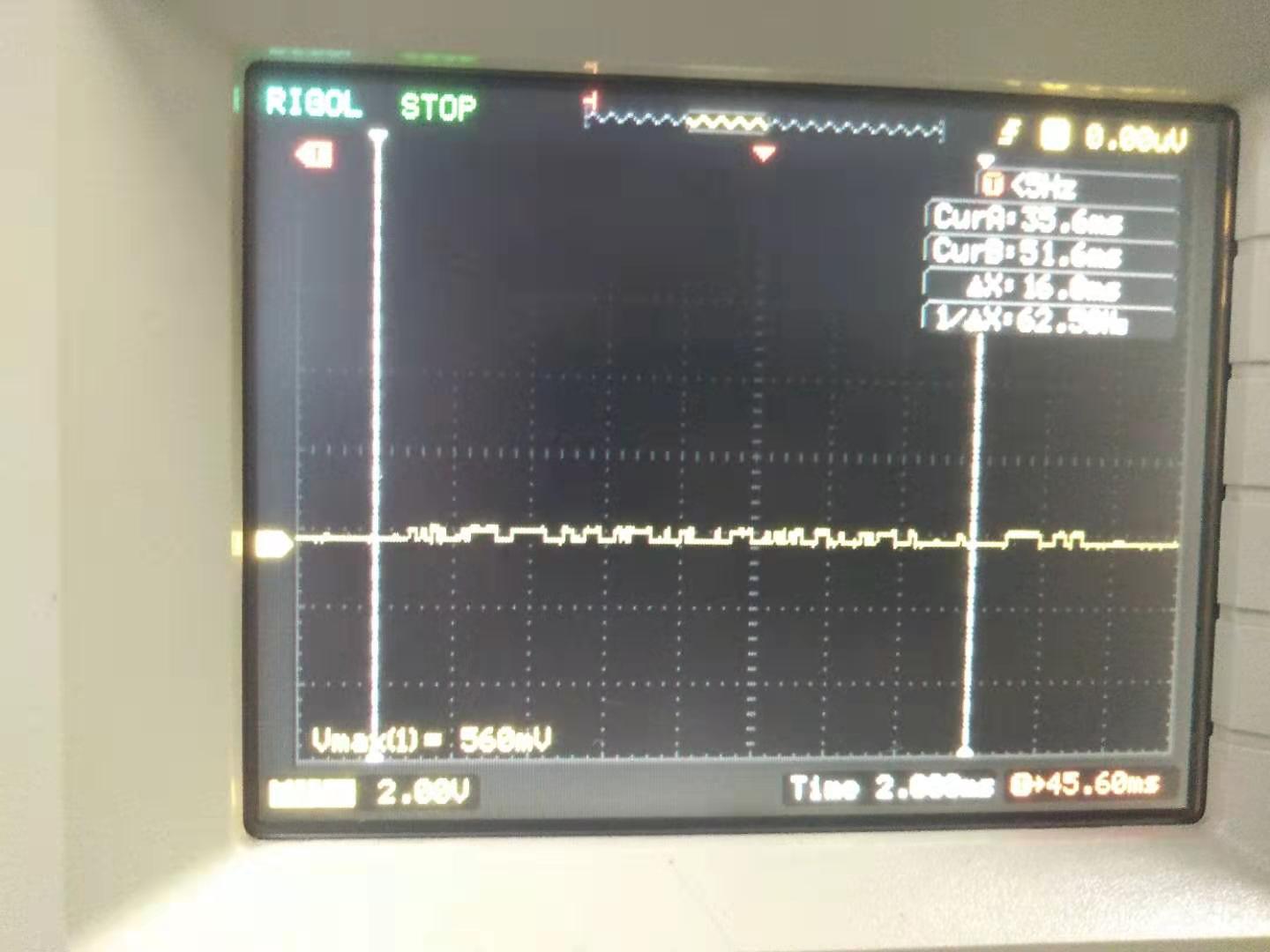
Design with DS8921 for RS422 Communications, When the host communicates with one  slave, it can send and receive data normally. When the host communicates with two slaves, the signal sent by the slave is pulled down (As shown in the picture), The host can not receive two slave feedback data.

Please help to solve this problem, Thanks!

  • Hi Blanche,

    Which signal is shown in your waveform capture?

    Could you please share a schematic showing how you are using this device and a high-level block diagram showing how master and slave nodes connect to one another?

    Regards,
    Max

  • Hi Max,

    The schematic as below:

    The previous waveforms captured the output signal of point Y.

    Thanks!

  • Thanks for the schematic.  Are you sure you are connecting the Y/Z outputs of the master to the A/B inputs to each slave, and the Y/Z outputs of each slave to the A/B inputs to the master?  And, are the slaves configured such that they can disable their output driver when not actively transmitting (so that other slaves can transmit via the same bus wires without interference)?

    Regards,
    Max

  • Hi Max,

    For the two questions you raised, I replied one by one.

    (1) The first question: The host is implemented by UT-890A. The hardware connection method is no problem, that is, the input RXD of the master is connected to the output Z/Y of the slave, the output T/R of the master is connected to the input A/B of the slave.
       (2) The second problem: First, the chip does not have the output control disable function;Second, the configured slave device  will feed back data to the master only  until  receivied  the data of  corresponding address . Simultaneously, only one slave device communicates  with the  master on the bus at a time.   Therefore,other slaves can transmit via the same bus wires without interference.

    Thanks!

  • Hello,

    For the second question I still have one concern.  Are the slave devices able to disable their output (i.e., make it high-Z)?  Or do they just hold it at a high or low state when they are idle (not responding to a request from teh master with their address).  If they used a device like U3 on your schematic in their design, for example, there wouldn't be any way to disable them.

    Assuming the slaves really are capable of going to a high-impedance state, can you please show us the A, B, Z, and Y signals on an oscilloscope for the cases where communication is working normally (one slave connected at a time) and when it is showing the issue (both slaves populated).

    Also, can you please confirm that the slaves are configured with different addresses?

    Thank you,
    Max

  • Hi,Max

    First, the DS8921ATM chip cannot disable the output.At the same time, the signal output of the chip cannot enter the high-impedance state.
    Second, each slave is configured with a different address.
    Third, when only one slave is configured, when the master does not send data to the slave, A outputing signal of the slave is 2.56V, B outputing signal of the slave is 2.48V, and  Z outputing signal of the slave is 5.04V. Y outputing signal of the slave is 240mV.
    Fourth, when two slaves are configured, one address is 0x01, one address is 0x02, the host sends data of address 0x01, A output signal is shown in Figure 1, B signal is shown in Figure 2, Z signal is shown in Figure 3, Y signal See Figure 4.

    Figure 1  A output signal

    Figure 2   B output signal

    Figure 3   Z output signal

    Figure 4   Y output signal

    As can be seen from Figure 4, the Y-side signal is pulled low.

    Thanks!


    Louisa Qian  钱璐

    Xi'an Chuanglian Electric Technology (Group) Co., Ltd.

    Tel:     (86)-29-8829-2785

    E-mail qian865786299@163.com

  • Figure 1  A output signal

    Figure 2   B output signal

    Figure 3   Z output signal

    Figure 4   Y output signal

  • Hi Louisa,

    Thanks for providing these waveforms.  Based on these, there are a few more things I'd recommend checking:

    1. It is possible that the Y output line doesn't properly connect from the driver output through the cable to the receiver input.  Can you please check for continuity of the connection using an Ohmmeter?

    2. It is possible that there is some kind of short-circuit to ground on the Y output.  Can you please measure the resistance to ground of this connection?

    3. It is possible that another device is driving the Y line low while this slave tries to toggle.  This would result in high output current - is it possible to check for this by adding a series resistance on the line and measuring the voltage drop?  This may be easier if you can force the output to a high state by driving DI high on the slave device.  (In that case, you might also be able to detect the larger output current by measuring ICC or by detecting whether the device heats up.)

    Also, can you please confirm that the slaves are all configured for full-duplex (four-wire) configuration, not half-duplex (two-wire)?

    Max

  • Hi Louisa,

    Have you been able to resolve this issue?  If not, have you looked into my comments above?

    Regards,
    Max