This thread has been locked.

If you have a related question, please click the "Ask a related question" button in the top right corner. The newly created question will be automatically linked to this question.

DS25CP114: External bias circuit required when used in AC coupled input connection ?

Guru 19775 points
Part Number: DS25CP114

Hi Team,

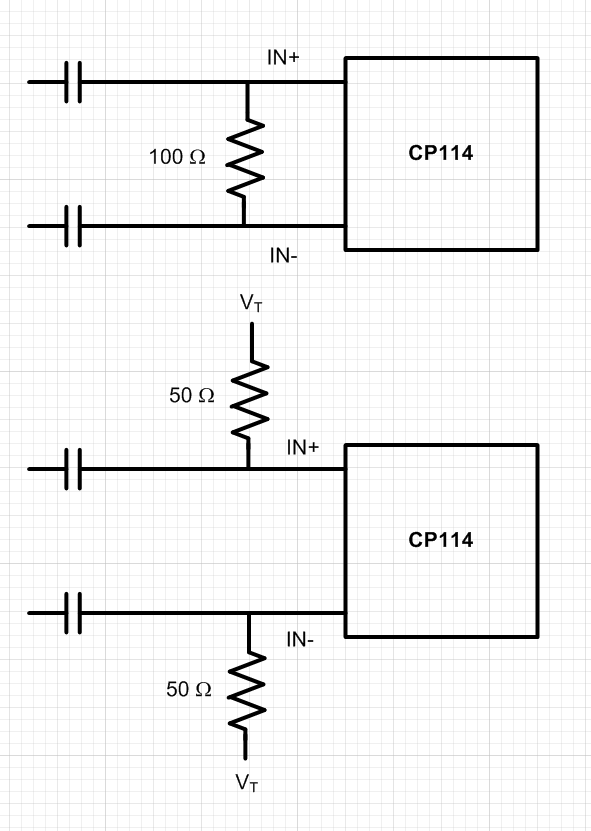
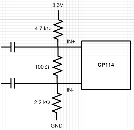
When AC coupling the DS25CP114 input, the device would require external 100ohm differential termination. Would you also need the external common mode bias circuit, too ?

Best Regards,

Kawai

  • Hi Kawai,

    The DS25CP114 would definately need to have a termination.  You should be able to bias it within the termination.  You could use either of these styles.  In most cases we just use a 100 ohm differential termination in the lab, but in a system the 2x50 ohm termination to Vt would have better noise immunity.  Vt can even just be GND.

    Regards,

    Lee

  • Hi Lee-san,

    Thanks for your advice.

    Q1). Based on the above schematic, do you mean that DS25CP114 has internal bias circuit ? What is bias voltage in this case ?

    Q2). Isn't the  recommended common mode voltage range, VCMR = VID/2 ~ Vcc-VID/2 ? Datasheet describes at the condition of VID=100mV.
    If we are biasing externally, I think VCM=0V would not be recommended. Input signal would go below 0V.

    Q3). Is the internal bias circuit different from DS25CP104 ?

    Best Regards,

    Kawai

  • Hi Lee-san,

    Could you please help us answer customer ?

    Best Regards,

    Kawai

  • Hi Kawai-san,

    The device does not have a bias circuit.  To guarantee a specific bias voltage on the input I would recommend a simple resistor divider as shown below.  We use the circuit without the bias successfully in the lab, but it does not have as much noise immunity.  The resistor bias approximates the normal LVDS 1.2V voltage on the input.


    Regards,

    Lee