This thread has been locked.

If you have a related question, please click the "Ask a related question" button in the top right corner. The newly created question will be automatically linked to this question.

TCA9543A: Selected Output I2C bus voltage at wrong value

Part Number: TCA9543A

Hi team,

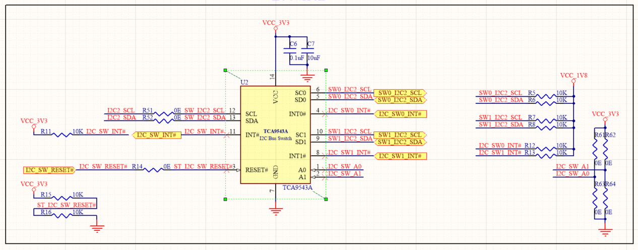
We are using TCA9543APW to split a 3.3V I2C bus to 2 different 1.8V I2C buses.

The input SDA, SCL lines are pulled up to 3.3V using 10K resistors. The SDA, SCL lines of both output channels are pulled up to 1.8V using 10K resistors.

When none of the output channels are selected, all these signal voltages are as expected.

When an output channel is selected, the SDA and SCL line voltages of that channel turns 2.15V.

Why is it so?

Please help urgently.

Thanks.

Emil Zacharia George

  • Hey Emil,

    Short answer: Vcc of the TCA9543A was selected improperly for your level translation application.

    Fix: change Vcc from 3.3V of pin 14 to 3V or lower (like 1.8V since you have a rail for it)


    -----------------------------Long answer---------------------------------------

    Our I2C switches/muxes use a pass FET architecture to provide the level translation feature.

    Our device will use the Vcc to supply the reference voltage at the gate of the pass FET when a channel is enabled.

    Lets walk through an example: Vcc =3.3V and secondary channels are set to 1.8V like in your case. Pull ups are 10k on secondary channels and main bus. We will assume Vth is about 1.3V based on figure 17 in the datasheet (3.3V-2V=1.3V).

    Note that to remove the parasitic body diode on the pass FET, I set two NFETs in series with the sources tied together.

    You can see when we enable the secondary channel (set gate voltage to 3.3V) the pass FET is turned on always and the secondary channel (labeled Chx) sees about 2V.

    This is because the 1.8V pull up at the source of the pass FET generates a gate to source voltage to the pass FET as 3.3V-1.8V = 1.5V which is larger than the Vth of the pass FET which is 1.3V meaning that the Pass FET is conducting. You can then think of the pass FET as a short so now you have a resistor divider with the 3.3V pull up resistor. Because the resistor divider voltage is larger than Vgate-Vth, the pass FET ends up regulating itself to clamp at 2V (3.3Vgate-1.3Vth =2V) to try to put itself back into the cut off region of operation.

    Now, if I want to fix this, I need to change the gate voltage to a lower level to ensure that the Chx pull up voltage when compared to the gate voltage when the channel is enable is less than the Vth ( we want Vgate_to_source to be less than Vth when enabled). I can do this by changing Vcc of the device to 3V or less ( will use 2.5V in my example).

    Now when the channel is enabled, the 1.8V stays regulated to 1.8V instead of seeing the always conducting pass FET which pulls the voltage higher due to the resistor divider and self regulated pass FET.

    Figure 17 shows how you should select Vcc for the I2C switch:

    Thanks,

    -Bobby

  • I used 1.8V as VCC and it solved the issue. Thanks.