This thread has been locked.

If you have a related question, please click the "Ask a related question" button in the top right corner. The newly created question will be automatically linked to this question.

TCAN1042HV: TVS selection

Genius 12760 points
Part Number: TCAN1042HV

Unfortunately I did not find any TVS diodes with 60V stand-off voltage and sufficiently small junction capacitance to realize the conventional protection circuit. As alternative I have found the following.

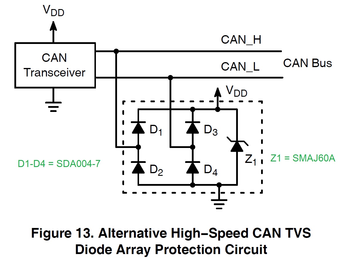
I would realize this with a SMAJ60A as Zener-TVS and a diode array like the SDA004-7.

  1. How do you judge this solution?
  2. Would you or would you not connect VDD with the 48V supply in this solution (advantages and disadvantages)?

Regards,

Bernd

  • Hi Bo,

    I'll review your proposed solution and get back to you with my comments tomorrow.

    Regards,
    Eric

  • Hi Bernd,

    I'm not too familiar with this type of protection scheme, but it appears to be a valid way to implement a protection circuit without introducing the typical amount of capacitance associated with tradition TVS diodes. Some of my concerns would include that it is more difficult to determine the circuit's standoff voltage and it would require the bus offset voltage (and subsequent noise) to remain between the supply voltages. With the connection to the 48v supply line, I would recommend ensuring that this rail is robust enough to handle the transients that would be passed to it during a clamping event. If the capacitive buffer of this rail is not large enough, noise may propagate through the system's supply.

    After looking into the matter further, I don't believe I would have much to add to the original article this figure was taken from. It paper includes advantages and disadvantages of the circuit and addresses the constraints of the CAN offset voltage. 
    EMI/ESD Protection Solutions for the CAN Bus

    Please let me know if you have questions about how this information may be used with TCAN1042.
    Regards,
    Eric

  • Bernd,

    Adding on to Eric's comments, I would be concerned as well if this protection scheme were used as shown with the diodes referencing a common "VDD" rail.  As the Zener clamps sink the surge currents the voltage across them would rise, and the lower-voltage devices (transceivers, MCUs, etc.) powered off of this rail may be adversely affected by the higher supply voltage.  From this standpoint replacing the "VDD" shown with something like a battery rail (which would be more heavily filtered at each node and regulated down to source more sensitive lower-voltage components) may be the safer way to go.

    I'd like to propose one other idea as well.  Could you place a capacitor in series with a lower-voltage TVS on each CAN line?  This would allow the system to withstand DC shorts on CANH/CANL within the transceiver's absolute maximum range, but would still look suitably "low impedance" to conduct any fast transient overvoltages that occur (e.g., due to ESD).  Since the series cap and the TVS capacitance would combine in series the capacitive loading seen by the CAN lines should be minimal.

    Regards,
    Max

  • Max,

    thank you for this hint.
    The solution with the series capacitor(AC coupling) was considered too.
    In which range should the capacitor be in this case?

    Regards,
    Bernd

  • Hi Bernd,

    It would depend on some of the specifics of the application.  The capacitance would need to be high enough to act as a low impedance for the different transients that the TVS is intended to protect against.  However, very high capacitances may result in higher stresses to the TVS when it needs to discharge following a "hot plug" event to a power supply.  So, these two factors would need to be balanced based up on the expected stresses and and the capabilities of the diode.

    Max