This thread has been locked.
If you have a related question, please click the "Ask a related question" button in the top right corner. The newly created question will be automatically linked to this question.
Hello,
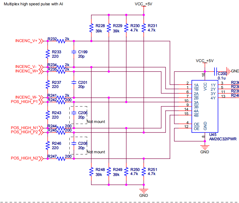
Our customer used AM26C32 for Servo driver application, and his application is singed-ended input, INCENC_V- connected VCC_+5V,INCENC_V+ connected signal source, but he found that the duty cycle is changed when the frequency is higher than 200Khz. So could you please help to analysis?
Below is the tested results and schematic:
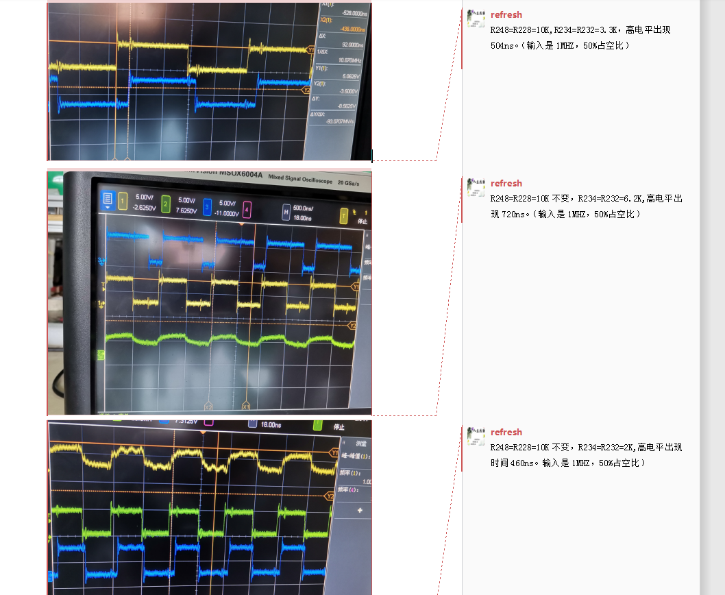
The three testes conditions are as this:
1)R248=R228=10K, R234=R232=3.3K, and the high level appears 504ns.(input is 1Mhz, 50% duty cycle).
2)R248=R228=10K, R234=R232=6.2K,and the high level appears 720ns(input is 1Mhz, 50% duty cycle).
3)R248=R228=10K, R234=R232= 2K,and the high level appears 460ns(input is 1Mhz, 50% duty cycle).
Best regards
Kailyn
Hi Kailyn,
Our team is currently out of the office due to the US holiday, but we will get back to you later this week.
Regards,
Max
Kailyn,
After reviewing the schematic and waveforms, I have several questions: 1) can you share a bit more about the single-ended signal, such as peak to peak voltage, common mode voltage, source impedance? 2) With the resistor network, some DC voltage difference will show between A and B pins. I'm not sure how to expect keeping 50% duty cycle with the DC offset. Can you help explain? 3) Could you capture the waveforms of A and B?
Regards,
Hao