This thread has been locked.

If you have a related question, please click the "Ask a related question" button in the top right corner. The newly created question will be automatically linked to this question.

DS90UB913Q-Q1: i2c communication problem

Part Number: DS90UB913Q-Q1

in our design, DS90UB913Q & 914 are set in passthrough mode,  my program set 914's slave1 & alias slave id to camera's ID address. PCLK is 12MHz

1)when debug the program, I found that I2C communication is not stable. sometime reading result is OK, sometimes is not as we expected.

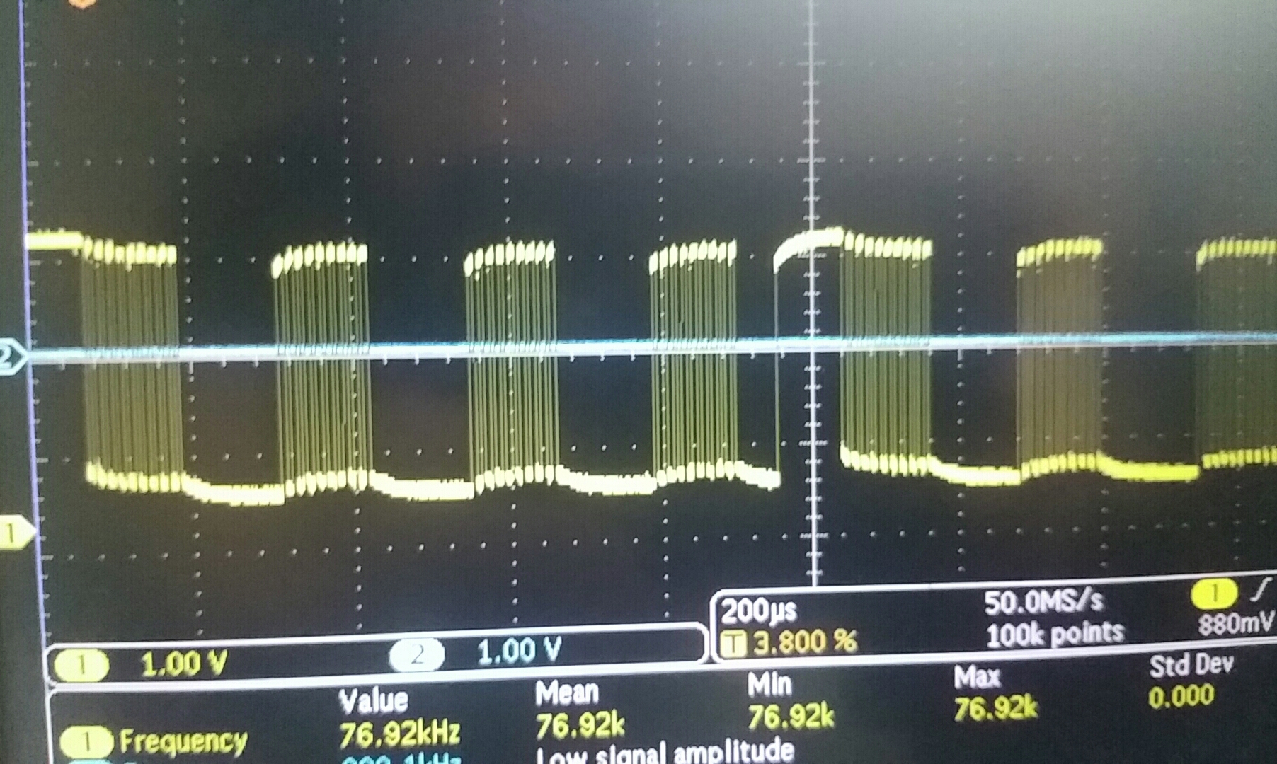
 I check the signal of SCL between 913 chips and camera module , the waveform is as following picture, looks like SCL signal cannot go to close to "0", SDA signal has the similar problem.

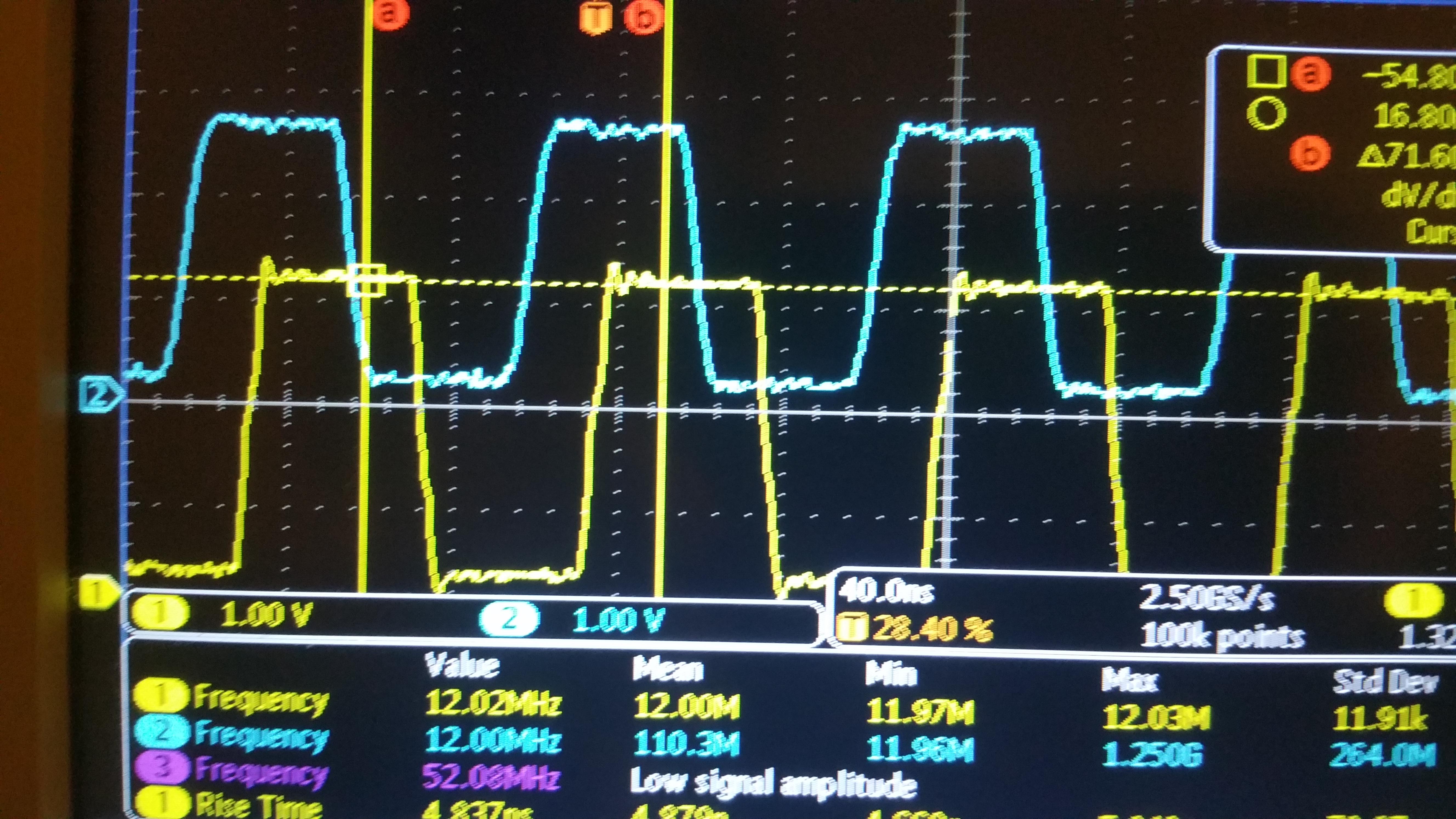
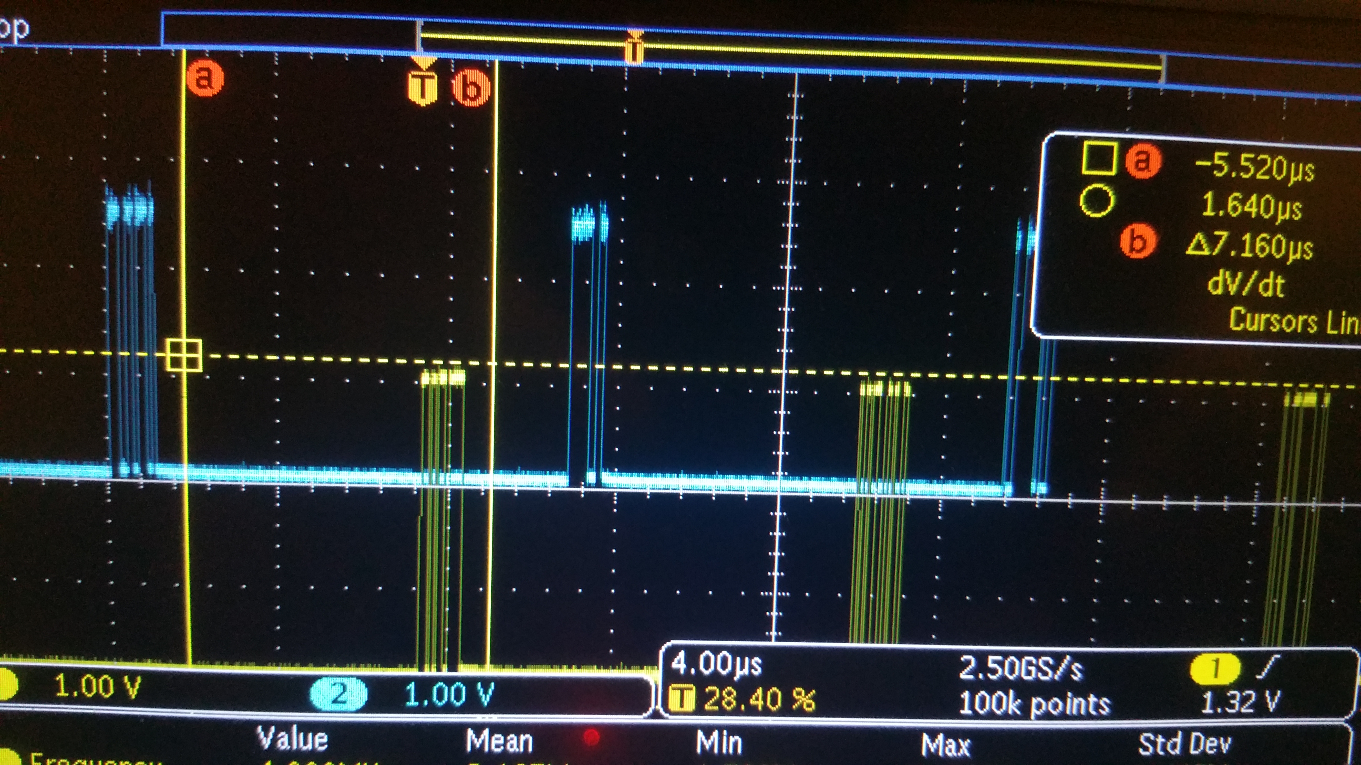
2) I compared the signals on camera side and 914 side, VSYNC on both side looks same and  has 8us delay,  HSYNC singal looks also ok, I can also see PCLK signal on 914 side without problem, but when I compare the pixel data signal D7 on both side, there are lot of  difference between them, not only delay. but 914's "lock" and "pass" signal are quite stable, I do not know why two sides data signal are different. 

thanks for help

  • pls check which mode is used here, raw10 or lf raw12?

    Steven

  • 12 bit low frequency mode 

  • Hello

    1. Please ensure you have sufficient setup/hold time on the Serializer Input side

    2. Please run a BIST test from Serializer 913 to 914 and comment on the result

    Thanks

    Vijay

  • Also, pls check 913a d/s page8, the minimum PCLK freq. is 25Mhz for LF 12bit mode. so please follow up 913a's d/s design request. 

    since your PCLK is only 12M in this case, this is out of chip electrical spec. request, so it could make the data pin no output.

    best regards,

    Steven

  • sorry, I did not get what you said, I checked the datasheet, on Page 8, under "8.3 Recommended Operating Conditions", PCLK is min 10MHz, max 100MHz. also, under 10.1 section, it is said "12 bits of DATA+2 bits SYNC for an input PCLK range of 10 MHz-50 MHz in the 12-bit low-frequency mode". so, PCLK 12Mhz should be OK.

    In datasheet, table 9 and table 10 mentioned 25Mhz, but I think is only BIST, is that correct?

    our design is following figure 46 in datasheet, both 913 and 914 are driving by 12MHz PCLK from camera module

  • It sounds your d/s is different from www.ti.com, pls check d/s page8 in www.ti.com (https://www.ti.com/lit/ds/symlink/ds90ub913a-q1.pdf), the minimum PCLK inside 913a is 25MHz @LF 12bits mode.

    btw, if you disconenct the PCLK input to 913A, does the i2c link work or not?

    regards,

    Steven

  • Hi, Steve,

    the chip we used is 914Q , not 914A. 914Q is 12MHz.

    current situation is that, even I2C signal looks not very good, the communication is OK, uC can read from and write to  camera by I2C .

    but, because PCLK is not valid between the frame signal, it cause 914Q's lock signal not stable, then the communication is lost. I asked this question in another post. 

    Thanks for your help.

  • Hi, steve

    I disconnected PCLK signal to 913Q, make it floating, then I2C link did not work, it can not communicate with remote camera module. 

    on 914Q side, lock signal is  not stable. on 914Q's pclk pin, I still can see waveform, sometimes it shows 26MHz clock signal, sometimes it is "0", what does this imply?

    Thanks

  • HI,

    1. What is your cable? is it STP? 913q only supports STP.

    2. please provide the PCLK in ub913q and pclk output in ub914q, do they have same freq.?

    3. can your run the BIST, does the link work well?

    4. if the data pin has error, it means the link doesn't work well, and error can be found.

    5. if you disable the PCLK input, the 913q would work in internal mode, and you can the lock pin is high in ub914q side if the channel is good.

    best regarsd,

    Steven

  • HI,steve.

    answer your quesiton first

    1, cable we using now are twisted ribbon cable, because length is just around 20cm, we think it should be fine, 

    2. PCLK on both side are 12MHz blue one on 913 side, yellow on 914 side

    3. I did BIST test before , it is OK

    now, I can control the remote camera and record the image data, but the data is not correct. I checked waveform of VSYNC and HSYNC, they looks ok, 7.1us delay, but the data signal D7 are quite diffent , I do not know why.

    1) this pic show VSYNC signal on both side, 914 side has about 7us delay than 913 side

    2) image data D7 waveform

    you can see the waveform are different.

    But here, I think the delay between two sides is just 7us, if delay is 7us plus one or more frame times, it is  meaningless to compare the waveform like this. 

  • harry,

    this sounds unreasonable since only data is wrong. can you try other Data pins in 913q and 914q respectively?

    if possible, can you ship one system to TI for test? thanks.

    regards

    Steven

  • Hi, Steve,

    I checked another data, it is also wrong.  it is so strange. We will see what we can do before we send it to you.

    Today, I found something else I do not understand,  1) with I2C, I can read/write 914 and remote camera, but today I tried to read 913, it always gave me "0", even register 0, ID address. :-(

    2) I checked differential signals between 913 and 914, it looks strange to me ,  yellow is D+. blue is D-, red is difference between them.

    3) which registers in 914 or 913  must to be configured in order to make the system work? now, I only configured the remote camera I2C address in 914 register, anything else are necessary? so far, I can read 914 and camera, but not 913. I am worried the bad waveform above maybe related with some register configuration?

    Thanks for help 

  • 1. no special reg. setting is required. for i2c, the general settings are i2c passthrough enable, deser alias, remote slave id/ alisas name setting, since you can visit remote slave i2c, i think these MUST setting should be right in your side.

    2. you can measure the high speed signal with good probe bandwidth for better waveform, this plot sounds good but not clear.

    Steven