This thread has been locked.

If you have a related question, please click the "Ask a related question" button in the top right corner. The newly created question will be automatically linked to this question.

DS90UB914Q-Q1: could PCLK frequency be invalid for a short moment?

Part Number: DS90UB914Q-Q1

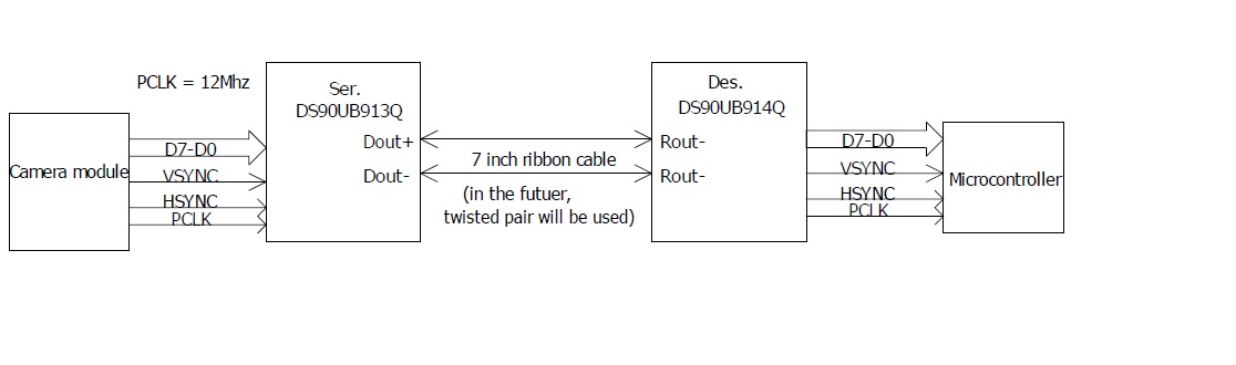
DS90UB914 and 913 work together, 914 is set to drive by PCLK.

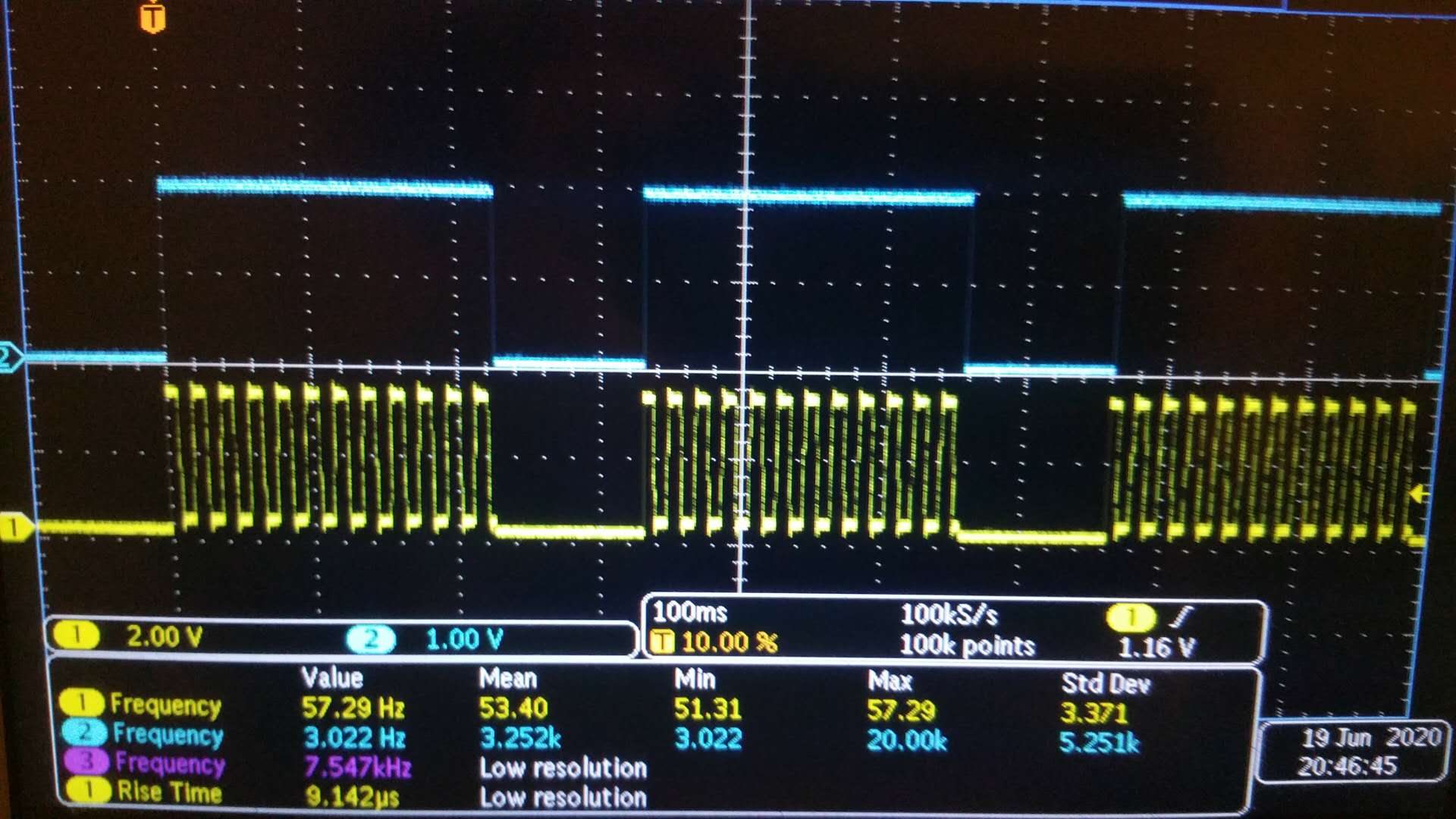
when debugging , I found that PCLK must be always available, otherwise I2C communication to remote camera will be wrong, but when configuring the camera, PCLK may  be not available for a moment, should software check pass and lock signal to before I2C communication? 

2) some camera module can set a few PCLK speed, so, in case pixel data is making the camera buffer full, PCLK can change to high frequency to send out pixel data faster, in this situation, will 913 and 914 still be working stable? thanks 

  • Hi Harry,

    When PCLK is not available, the serializer will establish link using the internal osc. It's always a good idea to verify lock before any remote I2C communication.

    It should be able to change PCLK speed as long as PCLK is within the limit.

  • Hi Jiashow,

    I am a bit confused about your reply to Harry's question:  "the serializer will establish link using the internal osc", Does the Ser 913 have an internal osc?

    From datasheet, my understanding to Ser 913 is: it only has two mode : PCLK or External Osocillator, Please be more specific and further about "internal osc"?

    Thanks

    Tom

  • Hello Tom,

    Yes 913Q has an internal oscillator. But as I mentioned in my previous post, the internal oscillator can only be used to establish the basic communication link between 913Q and 914Q. It can not be used to send video. For sending video you need to use one of the two clock modes you mentioned. 

    Best Regards,

    Casey 

  • Hi Casey,

    The problem for our debugging is that we can not have relaible I2C comunication between 913Q AND 914Q, when PCLK and external oscillator absent.

    I have further questions

    1. What is the frequency (data rate)  on the FPD-Link differential data bus  when using 913Q internal osc?

    2. Do the chip pair 913Q/914Q have termination resistor on chip internally (for the high speed impedance termination)?

    3. At hardware design, when we use relative long (say 10 meters) twisted pair cable for the FPD-Link communication between 913Q and 914Q, should we put a termination resistor (100OHM) 

    on EACH side of the cable between 913Q and 914Q?

    Thank you very much,

    Tom

  • Hi Tom,

    The 913A internal oscillator frequency is different in different modes and can range between 25MHz to 50MHz.

    The ICs have 100ohm differential termination at the RX pins and do not require additional termination resistor in STP mode.

  • HI, Casey,

    when the hardware starts, PCLK is always exists, so I2C communication to Camera without any problem. when after I configured the camera to the mode we want, PCLK signal becomes invalid between the frames, it cause the LOCK signal of 914Q is also not stable, LED hooks with LOCK signal starts flashing. you can see this on the pic, the blue line is 914's lock signal, while yellow line is the PCLK signal on 914 side.

    now I think  one solution is to make PCLK valid between the frames. I am wondering if there are any other solution to fix this problem? thanks for help  

    PCLK is 12Mhz, because time scale set to 100ms, it make PCLK  looks like running at very low frequency.

  • Hi Harry,

    I would suggest having a continuous PCLK.

    Jiashow

  • Hi, Jiashow

    I changed the PCLK to make it always available, and now I can control the remote camera and record the image. But the image recorded are not correct. Before,  our program is working to control local camera, it works fine and record the image data correctly, now in hardware, we put 913 & 914 between camera and controller,  program can also control the camera, but image not right. I do not know what to do next to debug this problem? any suggestion?

    Yours

    Harry

  • Hi Jiashow,

    I am working together with Harry Song on the same project. Having the same question as what he is asking now, I am attaching a PDF file showing our system's block diagram, trying to further explain what the problem we are experiencing.

    We are getting wrong image data at 914Q's output (D7-D0). This is the problem right now.

    To analyse this problem, we used oscilloscope 2 channels to compare the image data VSYNC, PCLK, and D7) at the 913Q image input end and  914Q's output end . We have seen the D7 is DIFFERENT, and the delay time of VSYNC is about 700ns. We are wondering if the delay time bwtween 913/914 is longer than oscilloscope's display sampling capability so we are we are seeing"out-of-display-frame" waveform. However,  anyway, we are getting incorrect data at the 914qoutput ends (image is wrong and we are sure camer is working properly).

    My two questions: 1. How long is the possibl maximum data processing time (delay), from 913Q input end to 914Q output end, would it be possibly longer than 700ns?

    2. what should the differential signal amplitude be, on the FPD link differential signals?

    Tom8081.default.pdf

  •  Hi Jiashow,

     I should have said the delay tiem of the VSYNc, from 913Q input end to 914Q output end,  is 7 us NOT 0.7 us. 

    Tom

  • Hi Tom,

    The serializer delay depends on the PCLK and mode and is specified in section 7.10 in the datasheet, where T is the period of the PCLK.

    The differential output voltage is between 640 and 824mV.

    Jiashow

  • Hi Ti support enginners:

    We are still in struggling of debugging DS913/914 system. We are suspecting the differential signals on the FPD link (DOUT+/DOUT-) have some issues. The attached image shows the oscilloscope's screen shot

    of the differential signal waveform (RED color, channel "M" , which is the subtraction of channel1 and channel 2, we do not have differential probe). The system is working based on PCLK  (12MHz) supplied by camera module.(circuit block diagram attached , too). the oscilloscope is 2.5GS/s, 300MHz bandwidth, Techtronix. The test point of this waveform is physically veay close to SER913 (~0.25" from it) on PCB, PCB traces are of 100ohm characteritic imepdance.

    We are stuck at this step: this differential signla waveform looks strange (we check grounding which is OK), communication between Ser 913 and Des914 is wrong.

    The first question here is: what kind of problem may cause such an unacceptable waveform? oscilloscope aliasing? grounding?  faulty/damaged chip? (The Ser 913 can still working to some extent).

    The 2nd question: we have tried using on-board ext oscillostor 12Mhz as the  oscillolator source to Ser913 instead of using camera's PCLK. One thing on the datasheet confused us: we changed the "Mode Resistor"

     for Ser913 TO 4.7k (EXT oscillator mode), but we are confused by the usage of register 0x35.  Is only setting "Rmode =4.7K" good enough to make Ser913 workis at  "Ext Mode oscillator Mode" ?

    What is the purpose of 0x35?

    Thanks a lot for your help.

    Tom

  • Hi Tom,

    Are you still seeing lock instability? 

    When you probe the FPD-Link, did you make sure only forward channel is running? I would suggest only measuring the 913 output when it's not connected to 914. You can probe one channel at a time (for example, only probe Dout+ to GND).

    Reg 0x35 indicates what the mode is selected by mode strapping. 4.7k should be enough. 

    Best,

    Jiashow