This thread has been locked.

If you have a related question, please click the "Ask a related question" button in the top right corner. The newly created question will be automatically linked to this question.

TPD1E05U06-Q1: Anode and cathode confusion

Part Number: TPD1E05U06-Q1

Hi. I have been using TPD1E05U06QDPYRQ1 in our design. they have been working all the time until a batch of PCBs we received (same revision) had shorts. We used a thermal camera and realized that the ESD diodes were the culprit. When we remove the ESD diodes the board would work. I decided to remove the ESD diode and put it on a breakout board and test it's characteristics. When I apply 5V on the "I/O" pad and return path on the GND line, my power supply would go into OCP and the voltage on the PSU would drop to 0.8V. It almost acted like the diode was being forward biased when in reverse bias. So I decided to switch around the connections. I was able to go all the way up to around 8V before it started conducting. at this point it really looked like the cathode mark that indicated the I/O pad was on the wrong side. I've never seen this before and maybe I am doing something wrong. I have two questions:

1) Is this something that has happened before? Where the marking was place on the wrong side?

2) If not, is my test setup correct? Am I doing something wrong?

Thank you,

JP

  • Hi JP,

    Welcome to E2E!

    I personally have not heard of this happening before, but I'll check with the team if this has happened before.

    Seems like when you flipped the device it operated exactly how it's supposed since 8V is withing the breakdown voltage range of the TPD1E05U06-Q1.

    Would you be able to share images of the device and describe the connections done for your testing?

    Best regards,

    Andy Robles

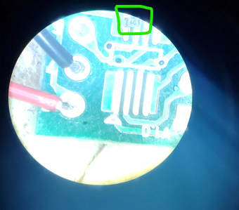
  • Below is a picture of the test setup. The green box is the DUT on a TSSOP breakout board. I did a continuity test and verified that the package marking side (on the left side of the device in the picture) is connected to the pad that goes to the red wire and the non-marked pad of the diode is connected to the pad that has the black wire on it (all shown in the picture below). In the first test I connected the red wire to the +ve side of the power supply and it started conducting when I got to 0.8V - 0.9V. I had the power supply limited to 20mA. I then switched the cables at the power supply (the red wire was now connected to the -ve side of the power supply) and it only started conducting when it got to 8V or so.

    I also noticed that there are a few posts that show other people encountering this problem.


  • Hi, any updates on this issue?

  • Hi JP,

    I apologize for the delay here, but I was able to talk to more people from the team and this particular device has had this issue before. Could you please reach out to me through email and in that email include all the information you have for the batch of device you have received? (Device markings on the top of the device, batch information that can be found in the packaging reel for the device, all the information that you may provide)

    I will go ahead and close this thread as we will continue our discussion through email.

    Best regards,

    Andy Robles

  • Thank you Andy. I'm looking forward to your email. 

  • Hi JP,

    I apologize for that. I meant to tag my email in the last response: a-robles@ti.com

    Best regards,

    Andy Robles