A related question is a question created from another question. When the related question is created, it will be automatically linked to the original question.
If you have a related question, please click the "Ask a related question" button in the top right corner. The newly created question will be automatically linked to this question.
Thank you for reaching out. Allow me to first address the current implementation as shown in your attached image, and then I will discuss replacing the TCA9800 with the TCA9617B.
Current Design (TCA9800)
Please note that the TCA9800 includes a built-in current source on the B-side, and thus should not have external pull-up resistors for the bus on this side, as any external current may affect the B-side low detection algorithm. In other words, the 3.3V bus should be connected to pin 8 of the TCA9800 without external resistors. Here is a generic example of an application of the TCA9800:
Please note the absence of pull-up resistors on the B-side. If the customer plans to implement the TCA9800, it would be necessary to connect the 3.3V rail to pin 8 and remove the two 4.7 kΩ resistors shown in your original drawing. This is necessary because the presence of the external pull-up resistors causes additional current that could violate the device’s IILC requirement (see TCA9800 datasheet section 9.4.1 “Device Operation Considerations” for more information).
Furthermore, consider the impact of the 22 Ω series resistors in your customer schematic, which would make it harder for the TCA9800 to perform well. An additional note on these resistors is below.
Replacement Considerations (TCA9617B)
The TCA9617B has a standard open-drain configuration for the bus, so external pull-up resistors would be needed if using this device. In other words, your drawing is better-suited for a TCA9617B than a TCA9800.
Here are some things to consider:
The TCA9617B’s standard configuration means that there is a 0.5 V static voltage offset for the B-side. You should ensure that this VOL of 0.5 V is compatible with your slave devices on the B-side of the repeater. Additionally, these devices should provide VOL of 0.4 V or lower, which is necessary to meet TCA9617B’s requirement for VILB.
The 22 Ω series resistors that are shown near the slave device would possibly degrade the performance of the TCA9617B. When the slave device pulls low, the 22 Ω and 4.7 kΩ resistors act as voltage dividers. Though the bump is small, a slave with a weak pull-down might produce a VOL shift that would cause a failure of the device to recognize and pass a low.
Like the TCA9800, this device is not “symmetrical” between A and B. The TCA9617B requires that VCCA ≤ VCCB. The customer must ensure that, in this application, the A-side is connected to the lower-voltage rail and bus.
Minimum VCCB for the TCA9617B is higher, but still compatible with this design. Note that replacing with TCA9617B would raise the VCCB minimum from 1.65 V to 2.2 V.
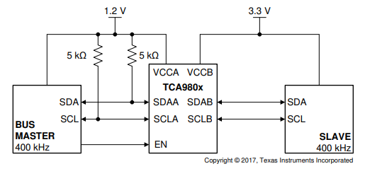
Here is a typical application of the TCA9617B. You may note that this is very similar to the drawing you provided:
As final considerations, note that the TCA9617B has slightly higher power consumption (i.e. higher quiescent supply current), similarly good timing/delay characteristics, and notably better startup time after raising the EN pin. Most beneficially, however: the TCA9617B allows for Fast Mode and Fast Mode+ (up to 1 MHz) and also permits higher bus capacitance (up to 550 pF on a 1 MHz I2C bus line) – both of these parameters would be improvements to the offerings of the TCA9800.