This thread has been locked.

If you have a related question, please click the "Ask a related question" button in the top right corner. The newly created question will be automatically linked to this question.

DS90UB954-Q1EVM: I2C Read Issue of Remote Slave Device Attached to DS90UB953-Q1EVM I2C Bus

Part Number: DS90UB954-Q1EVM
Other Parts Discussed in Thread: DS90UB953-Q1EVM, , ALP

I am working with the DS90UB953/954 Serializer/Deserializer EVM boards and a CMOS image sensor that needs to communicate over i2c with a USB dongle. My setup consists of the following:

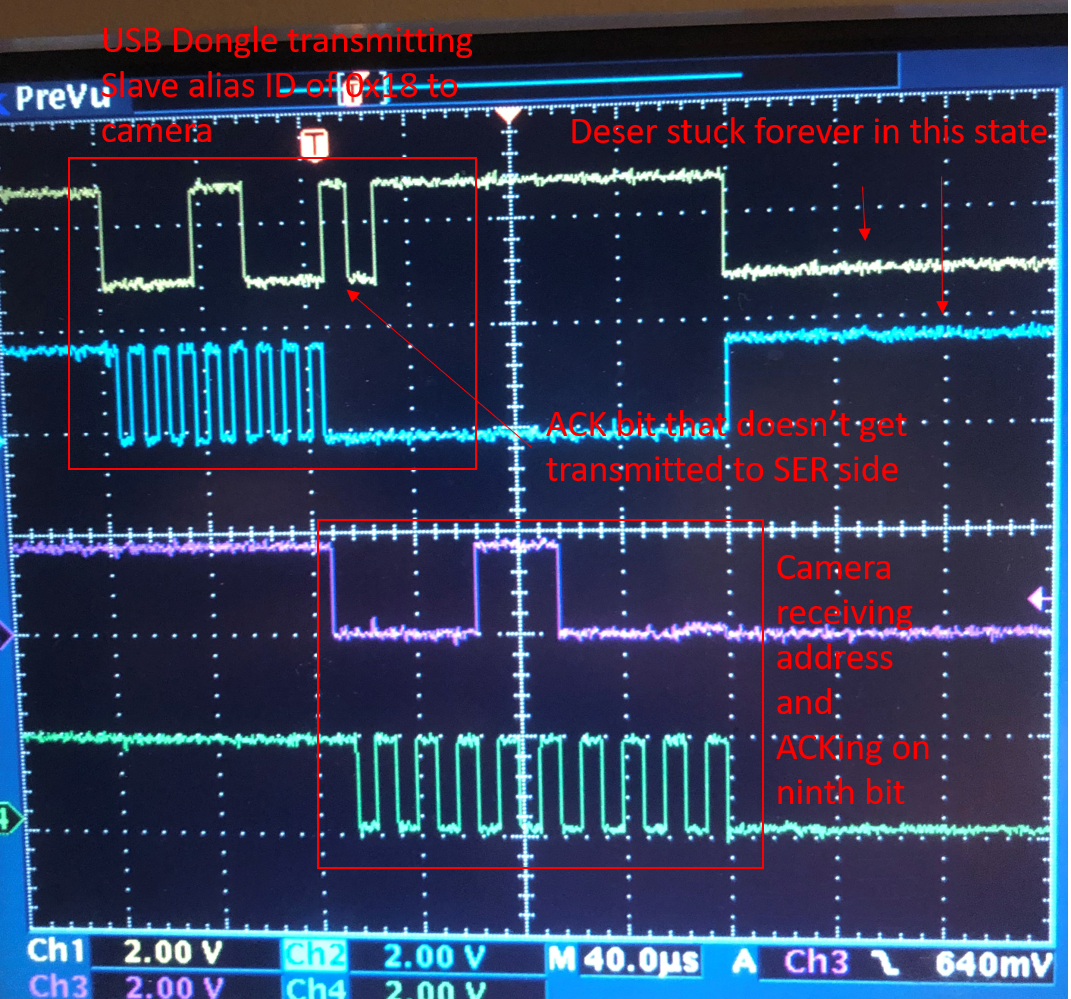
USB Dongle -- i2c connection---> DS90UB954-Q1EVM Deser ---> FPD LINK (Coax connection) --> DS90UB953-Q1EVM Ser -- i2c connection ---> CMOS Image sensor

The USB dongle (on the same local i2c bus as the Deser) needs to be able to read and write to the image sensor, located on the other i2c bus (with the serializer) across the FPD link

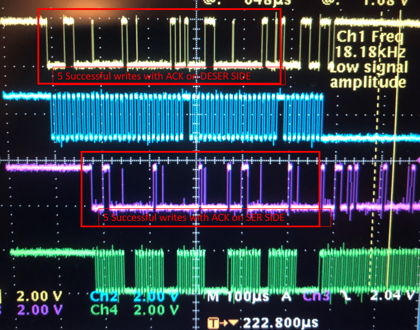
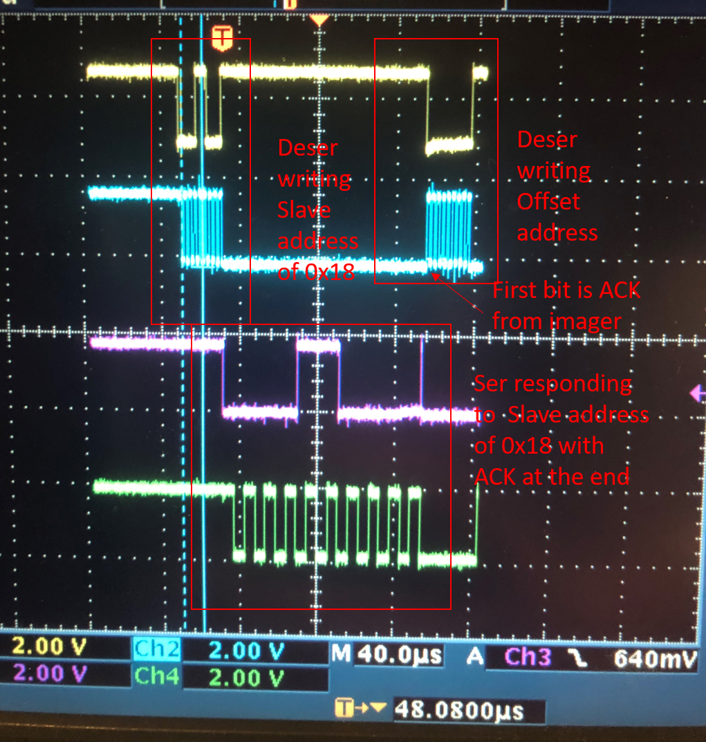
Right now, I have the i2c writes working, the USB dongle can write commands to the image sensor (using a slave alias ID of 0x18 to write to a physical address of 0x18 on the other side) and the image sensor ACKs these write commands. So the i2c passthrough is at least working on the back channel. I had to change the SDA and SCL high times on the serializer side so that it is slightly faster than the deserializer side in order to stop i2c packets from getting dropped on the SER side.

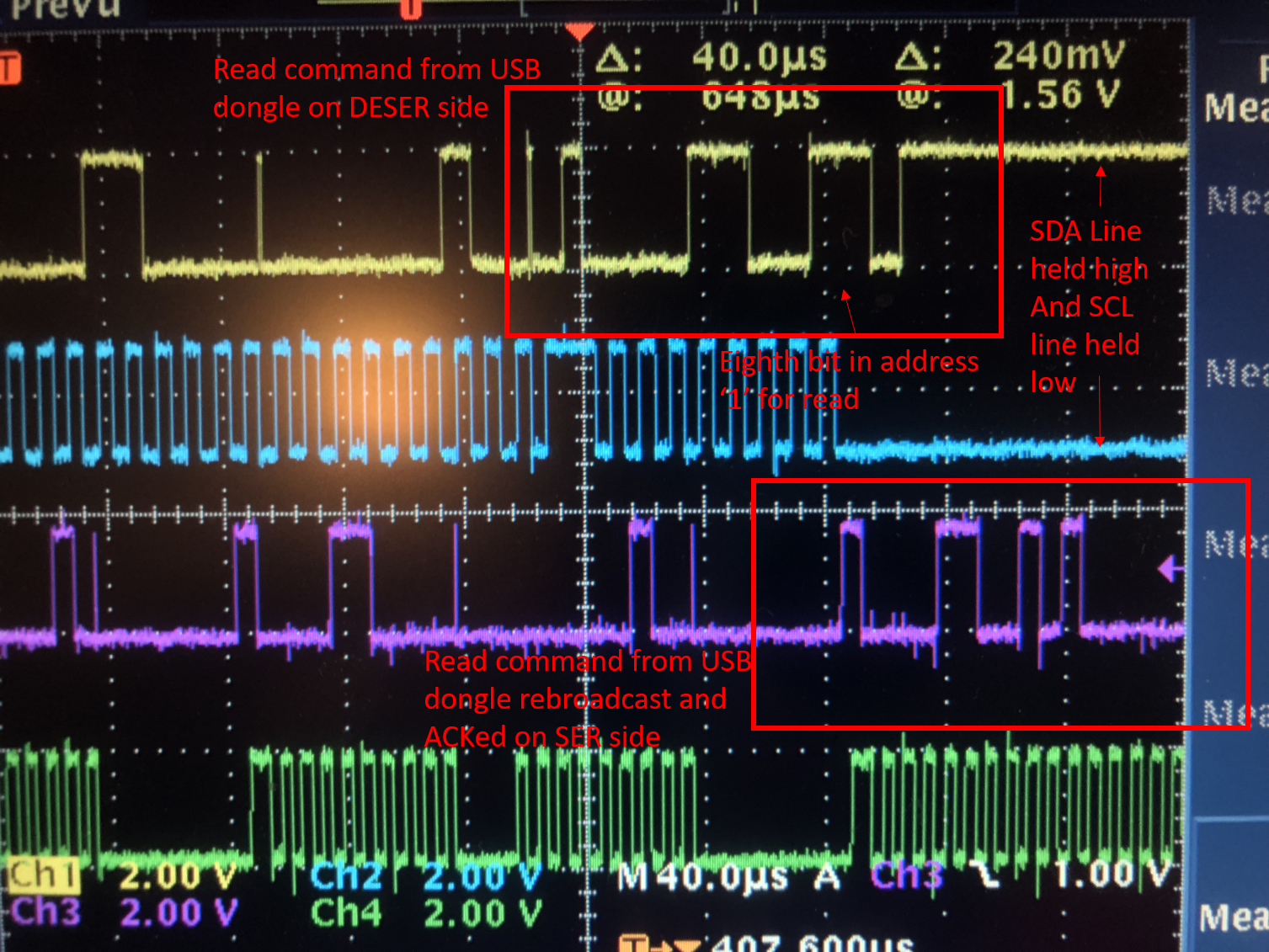
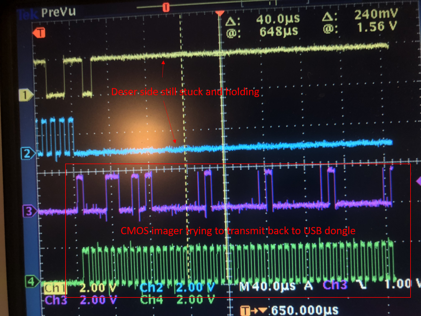
However, the USB Dongle also needs to read register data from the image sensor using an i2c read. When the USB Dongle attempts a read, the image sensor responds and attempts to send register data across the forward channel back to the dongle, but the data is never retransmitted back on the deser i2c bus. Instead, the deser just stretches the SCLK line for the amount of time specified in the BCC_WATCHDOG register (0x07).

Is there a setting I possibly missed that will enable the bidirectional communication to work with i2c across the back and forward channels? 

  • Hi Matthew,

    Let me clarify, you have no issues with writing to the imager but you'll seeing watchdog timer run out for when you read the imager? 

    Are you using the on board MSP430 and our Analog LaunchPad Gui? Or are you using a different software/MCU?

    If you're using a different software, can you make sure clock stretching is supported? Refer to section 7.5.3 in the 954 datasheet.

    Best,

    Jiashow

  • Hello, 

    Yes, that is correct, I can write to the imager just fine using the I2C passthrough and slave alias ID of 0x18. The imager acks the write commands just fine on the remote Serializer side. When I try to read the imager, the USB dongle transmits the 7 bits for the alias ID on the Deserializer side, then a '1' for read and then just hangs for the amount of time set in the watchdog counter register. 

    The imager on the serializer side sees the read command and attempts to respond with its own register data. It starts transmitting its register data which should be sent back across what I assume is the forward data channel, back to the deserializer. However, the imager's data is never rebroadcast back on the deserializer i2c line for the USB dongle to see. It just exhibits the hanging behavior that I described previously. 

    I am using the Analog Launchpad GUI

    Thank you

  • Hello,

    Are you using Analog Launchpad to write to the imager?It doesn't look like the issue is with the forward channel sinnce when you write imager data, the imager sends an ACK through the forward channel and you're able to receive it.

    When you probe the Imager I2C lines, what does the scopeshot look like?

    Does the imager have 16-bit address or value? Did you follow the examples below?

    Example 1:

    board.WriteI2C(0x60, 0x00, [0x01, 0x35])

    • I2C address: 0x60
    • Register address: 0x0001
    • Write register value: 0x35

    Example 2:

    board.ReadI2C(0xC4, 0x31, [0x29, 0x01])

    • I2C address: 0xC4
    • Register address: 0x3129
    • Read one byte data from register

    Example 3:

    board.WriteI2C(0xC4, 0x31, [0x29, 0x80, 0x02])

    • I2C address: 0xC4
    • Register address: 0x3129
    • Write register value: 0x8002

    Example 4:

    board.ReadI2C(0xC4, 0x31, [0x29, 0x02])

    • I2C address: 0xC4
    • Register address: 0x3129
    • Read two byte data from register

    Best,

    Jiashow

  • Hello, thank you for your reply

    Here are some screenshots of the commands that my USB dongle is sending over to the CMOS imager:

    Legend:

    Yellow - SDA line on DESER i2c bus (i2c bus containing USB dongle)

    Blue - SCL line on DESER i2c bus

    Purple - SDA line on SER i2c bus (i2c bus containing CMOS imager)

    Green - SCL line on SER i2c bus

    This first image shows 5 successful writes from the USB dongle to the CMOS imager. The imager has a 7 bit address of 0x18 and can be seen in the 1st and fourth octets below (the really short spikes are ACKs from the CMOS imager)

    The second image below shows an unsuccessful  read command from the USB dongle to CMOS imager. You can see that the Deser just holds the SDA line high and the SCL line low and the ACK never shows up from the read command to the CMOS imager. The CMOS imager gets the read command and ACKs on its side of the FPD link and starts trying to transmit data back to the Deser side. This data from the CMOS imager, however, is never received back on the Deser side (third image) 

    I will try those examples next 

    Thank you

  • Seems like the images didn't post so I attached them here

  • Hello,

    It looks like the slave is holding the SCL line low. Does the slave release the SCL line at some point? Is the data should be transmitted after the SCL line is released? If you turn off watchdog timer (reg 0x7) does it help?

    While this is for a different FPD link device, we have information regarding I2C in this app note: 

  • Hello, I changed some settings in the Deser to turn the auto ACK off so that the i2c sequence looks more like figures 5 and 6 in that application note that you posted. In the images I had posted earlier, I had auto ACK turned on on the Deser side and I dont think that is what I want. But I am still having an issue and I have narrowed it down to a few possibilities. See below.

    I loaded register settings into the Deser that assigned an alias ID of 0x18 to a physical ID of 0x18.Then, when I clicked on the Remote Registers tab in the ALP software and selected RX port 0 and clicked "Display", the Deser attempted to ping address 0x18 (which it thinks is the Ser address). Because I assigned an alias ID of 0x18 to a real ID of 0x18, the CMOS imager responded to the "Display" command, not the SER. And lo and behold, the i2c communication actually seemed to work! See the image below: 

    The SCL line is held low on the Deser side while the Ser side is transmitting to the camera, stretching the clock. The camera ACKs on the Ser side and the i2c sequence continues on the Deser side with the ACK bit first and the offset address (third octet in image). The i2c sequence continues after what is shown in the scope trace and it closely resembles the sequence shown in Figure 6 in the application note, so I believe the Deser itself can read and write from the camera.

    However, when I now try to do the same thing with the USB dongle, I still get that hanging behavior where SDA stays high during the slave device transmitting and then goes low indefinitely. Likewise, SCL goes low during slave device transmission and then goes high indefinitely. During this stuck period, the Deserializer goes unresponsive and cant be reached anymore with the ALP software. See the image below:

    The i2c sequence never continues past this point.

    My question is this: Do I need to make the i2c baud rate a lot faster on the DESER side than it is on the SER side like in the first image in order for this to work? Or does my USB dongle not support clock stretching and that is causing the problem ? 

    A few things:

    -I have turned off all watchdog and i2c line timers on both the Ser and Deser. 

    -Auto ACK is off on the Deser and Ser sides 

    Thank you 

  • Hello,

    The I2C buad rate isn't an issue as long as on the deserializer, it's the same or slower than the rat on the serializer side.

    When you say USB dongle, what exactly are you referring to? It's not the USB cord with MSP430 right? It's possible dongle doesn't support clock stretching.

    Best,

    Jiashow

  • Hello, 

    By USB dongle, I mean a separate device that is on the i2c bus with the de-serializer. It is a non-TI product. It communicates with a software program over USB that controls the CMOS imager. It is the end path for the image data from the camera coming out of the de-serializer and the "Host I2C" in the topology below:

    My last question before we can close out this issue is this: if my USB dongle doesn't support clock stretching, is there an easy workaround with that? 

    Thank you for all your help 

  • Hi Matt,

    I don't think there's a workaround for this. The remote devices take some time to communicate that's why we recommend clock stretching has to be supported.

    Best,

    Jiashow