- Ask a related questionWhat is a related question?A related question is a question created from another question. When the related question is created, it will be automatically linked to the original question.

Original question:

Hi team,
I am writing to seek help for RGMII standard, especially the TX_CTRL.
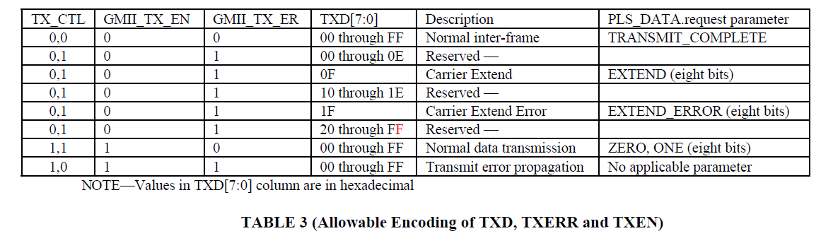
In DP83TC811s datasheet, RGMII interface TX_CTRL true table is shown below. When data comes, TX_CTRL/RX_CTRL should change between 1 and 0. At the negative edge of TX_CLK, the TX_ER should be low.
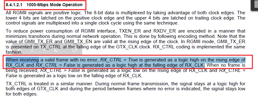
But from DP83867is datasheet, when in RGMII is used for 1000M mode and no error, RX_CTRL should always high.
Below is the testing waveform, Blue is TX_CTRL and yellow is TX_Dx, it conflict with our datasheet, which causes the IP error.
Could you please analyze why RGMII in two datasheet are different? Is there something misunderstand?
Thanks a lot.
Best regards
Chen