This thread has been locked.

If you have a related question, please click the "Ask a related question" button in the top right corner. The newly created question will be automatically linked to this question.

TCAN1145-Q1: INH-pin pull-down register

Part Number: TCAN1145-Q1

Hello Experts,

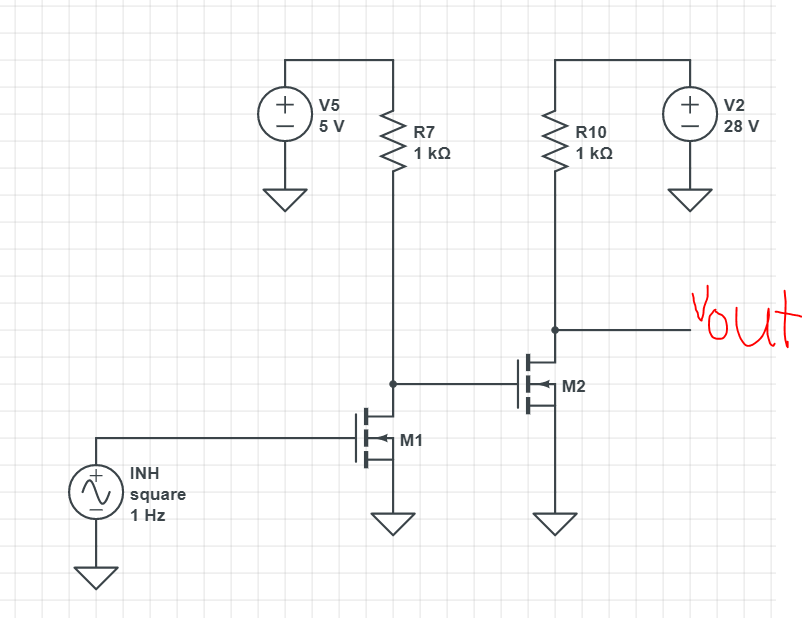
I would like to understand about INH-pin. The datasheet specify Rpd for INH-pin. INH-pin has pull-down resistor? Or this spec is for the external pull-down resistor? If the external pull-down resistor is required, why it is needed and why it is selected?

Best Regards,
Fujiwara

  • Hi Fujiwara,

    The INH pin does not have an internal pull down. The INH pin acts as a high voltage output from Vsup. It can be used to control the enable of a voltage regulator. If you would like to use it for that case that is when you would need an external pull down resistor of value Rpd. If you are not using the pin you can leave it floating. Keep in mind that this pin should be treated as a high voltage logic output and not a power output. 

    If you would like to read more about the pin section 10.3.5 on page 24 of the datasheet goes into more detail.

    Best,

    Chris

  • Fujiwara-san,

    To add on to what Chris said, the external pull-down isn't totally necessary. It is recommended because when INH is disabled (in sleep mode) the net is left floating internally rather than driven low. Because of this, we recommend a high-valued external pull-down resistor to give a strong discharge path to ground so that the voltage quickly discharges to 0V when it is disabled. And the reason the resistor is high valued is so there isn't significant current draw from VSUP.

    Regards,

  • Eric-san and Chris-san,

    Thank you for your comments, I understand.

    Customer would like to use INH-pin to drive a gate of external FET as following circuit. Would you please review it whether it would be work?

    https://tidrive.itg.ti.com/a/T1lKBsNZShVdWUoc/14079bb4-f4ad-4e01-a344-ae658d3a4d7f?l

    Best Regards,
    Fujiwara

  • Hi Fujiwara-san,

    Let me know if I am not understanding the circuit correctly. It looks like this is a method to apply power to your voltage regulator when the CAN device is powered up. However this can be accomplished if your Voltage regulator has an EN pin. Is there no EN pin on the voltage regulator?

    It doesn't look like this mosfet circuit would work.

    When a voltage is applied to the gate of M1 the switch would close but there is no voltage from the drain to source of M1. So no voltage would be applied to the gate of M2. Here is my recommended setup.

    Here is what it would look like in your circuit.

    Let me know if you have any questions about this, I know the hand drawing is not the best but the circuit above should be easy enough to follow.

    Best,

    Chris