Part Number: TPS65987D
Other Parts Discussed in Thread: TUSB8041, TUSB321, TPS2500
Hi,
The past months we've been working on the development of an USB Type C Docking Station to connect multiple devices to a Phone, with the possibility of connecting a charger to the system.
A Brief functionality:
- A phone is connected to the first PD controller (TPS65987DDH) bij an USB Type C connector. This controller is in Power Sink mode when no charger is connected to the system; i.e. it powers the hub and the connected devices. The controller is always in UFP mode.
- The data lines of the phone port are connected to a hub (TUSB8041)
- Two USB Type C connectors are available to connect devices (e.g. camera, flash drive, mouse, keyboard, etc) to the hub. Both are powered from the 5V supply, 500mA max. (TUSB321 with TPS2500).
- Another PD controller is present on the board (TPS65987DDH) to connect a charger (USB Type C) to the system. When the charger is connected is must power the system and the phone goes into charging mode.
- The phone will always be connected to the board.
- No battery is present on the board. One of both PD controllers will start in Dead Battery mode
- PP_HV1 and PP_HV2 are in dual link (both PD) and connected to an internal 5V supply rail. A SMPS makes 1V1 and 3V3 for internal use.
- A connection from Phone PD to Charger PD is present on GPIO1 with a pulldown resistor and a RC filter (1k/100nF).
Configurations Phone PD (Advanced mode):
- Boots in BP_WaitFor3V3_Internal; so when the Board_3V3 is stable, the PD controller loads its configuration from flash
- PP Switches as Sink or Source
- Power Duo Mode
- GPIO1 configured as input: Load App Config 1
- Load App Config 1 triggers CMD on rising edge: DBfg (clear dead battery flag) => so the flag clears when the charger is in Sink mode
- Load App Config 1 triggers CMD on rising edge: SWSr (swap to source)
- Load App Config 1 triggers CMD on rising edge: SWSk (swap to sink)
- Process & Initiate Swap to Source is enabled
- 1 Transmit Source capability is configured
- 1 Transmit Sink capability is configured
Configurations Charger PD (Advanced mode):
- Boots in BP_NoWait; so it always tries to load its config from flash
- PP Switches as Sink only
- Power duo mode
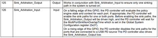
- GPIO1 is output: Sink Arbitration output
- Process & Initiate Swap to Sink is enabled
- 1 Transmit Sink capability is configured
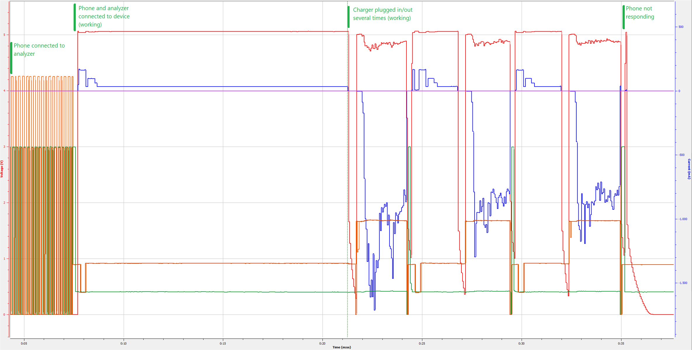
The device is used with the board permanently attached to the phone. The charger is only connected when charging the phone, not in operation. Most of the time it works as expected, but sometimes the Phone-PD becomes unresponsive. Only a hard reset of the phone, or an disconnect/connect can resolve the issue.
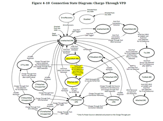
Using the debugging tools, I discovered that the state the Phone-PD is in when it is unresponsive is: COMMON_STATE_ATTACHWAIT_SNK.
Another issue: sometimes the Phone-PD is reponsive, but it is in PEState_Sink_Ready, or PEState_Legacy. In this case the phone can power the board, but it is not charging when the charger is connected. It looks like both PD controllers are in Sink mode (PP1_RCP in the charger is true).
When the device is working, the Phone-PD is in PEState_Source_Ready and PRState_Source_SinkTxOk.
When I hard reboot the phone (without changing anything on our device), the Phone-PD continues and negotiates a PDO with the phone.
Already tried:
- Using simple mode configurations
- Use Sink Arbitration Input on Phone-PD
- Use both - app config, Sink Arbitration input - on same input from Charger-PD
- Tried Virtual device configurations for Sink and Source in Phone-PD
- A lot of configurations regarding Port configuration and control
- Faster / slower slew rates
- Other phones
Unfortunately this also doesn't solve the issue.
Am I missing a things? Does anybody has a clue?
Kind regards,
Matthijs

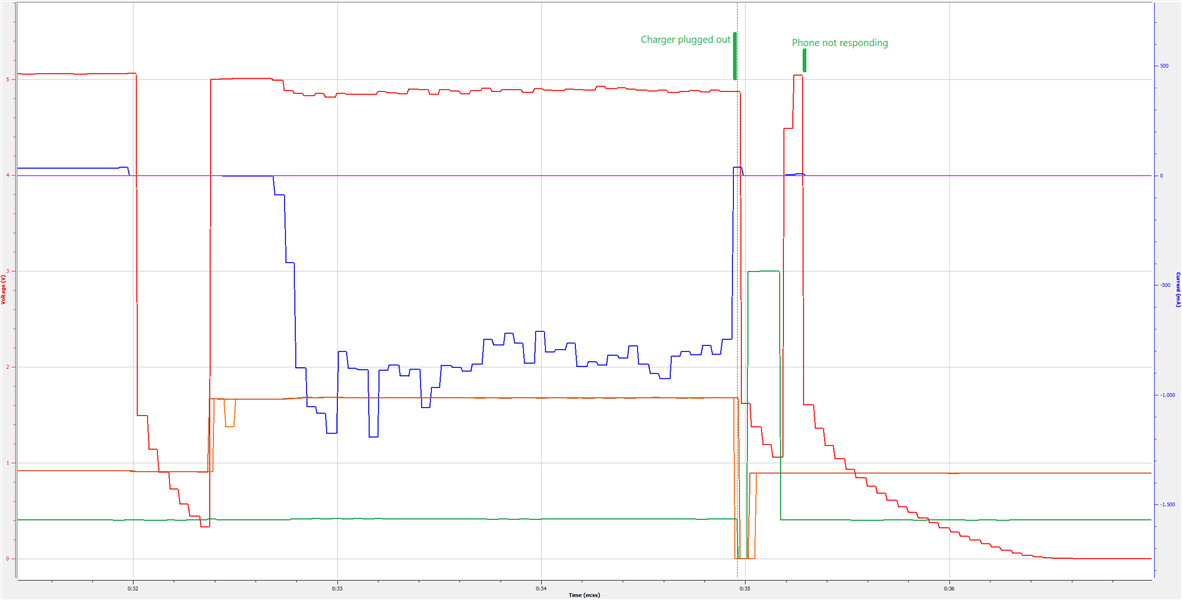

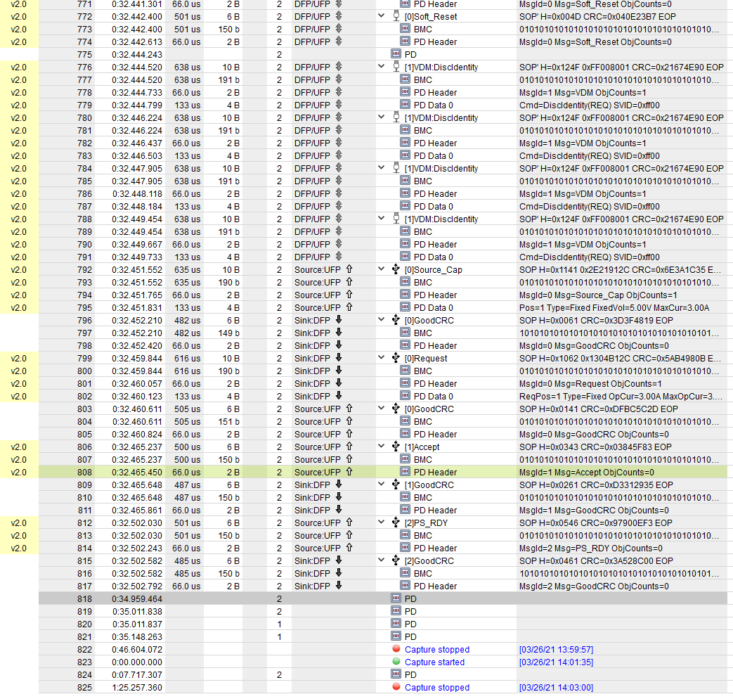 Line 818 through 821 are the last packets sent by the phone. After that moment, it doesn't respond anymore.