This thread has been locked.

If you have a related question, please click the "Ask a related question" button in the top right corner. The newly created question will be automatically linked to this question.

TUSB216IEVM: EVM schematic question

Part Number: TUSB216IEVM
Other Parts Discussed in Thread: TUSB216, TUSB216I

Dear team,

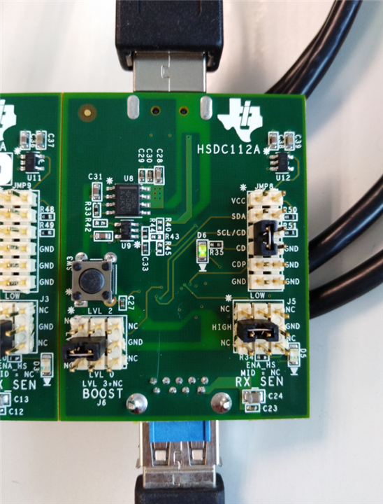
I get your TUSB216IEVM demo board today, but seems it can’t work normally. No matter how I modify the BOOST and RX_SEN config, the test result are same, looks like TUSB216 IC don't improve signal quality.

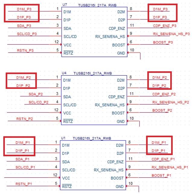
And I also download the user’s guide from TI web, and I find the input D+ and D- lines are short to the output D+ and D- lines on schematic, I check the input and output with multimeter during demo unpowered, they are short together.

Could you please tell me why we design like this, this will bypass TUSB216, and lose signal quality improve function.

Thanks & Best Regards,

Sherry

  • Hi Sherry,

    Yes, the TUSB216I works on the shorted DP/DM lines.  That is expected.  

    Can you install the jumper on the SCL/CD pin to  the CD LED and a jumper on the RX_SEN/ENA_HS pin to the LED and let me know which LEDs are lit during the test?  It is possible the redriver is not entering active mode.

    Are you running a compliance test?  If so are you following the USB compliance test procedure from the datasheet?

    Regards,

    JMMN

  • Hi JMMN,

    Thanks for your reply!

    Please check below picture, the D6 is lit, and I also check the waveform between D6 and R35, it was a constant voltage value. D5 is not lit because the jumper is in the wrong place.

    The customer is not running a compliance test, they just use LeCroy device to check USB eye pattern, and no any improvement no matter how they modify the BOOST and RX_SEN config.

    It seems TUSB216 doesn't enter active mode, how to enable the active mode? 

    In addition, why 216 works on the shorted DP/DM line? In this way, our device has no use in my understanding.

    Thanks & Best Regards,

    Sherry

  • Hi Sherry,

    Yes, the TUSB216I is designed to compensate the USB high speed signaling while shorted to the DP/DM lines.

    If the customer is taking eye diagrams, that is considered compliance testing since it is high speed signaling without a HS handshake.  Please follow the instructions in the datasheet so that the TUSB216I can enter compliance mode.  Please note that the test fixture needs to be connected to the TUSB216I before the test packets start to properly be enabled.

    Regards,

    JMMN

    The following procedure must be followed before using any oscilloscope compliance software to construct a USB High-speed Eye Mask: 8.2.2.1.1 For a Host Side Application

    1. Configure the TUSB216I to the desired BOOST setting

    2. Power on (or toggle the RSTN pin if already powered on) the TUSB216I

    3. Using SMA cables, connect the oscilloscope and the USB-IF host-side test fixture to the TUSB216I

    4. Enable the host to transmit USB TEST_PACKET

    5. Execute the oscilloscope USB compliance software.

    6. Repeat the above steps in order to re-test TUSB216I with a different BOOST setting (must reset to change)

    8.2.2.1.2 For a Device Side Application

    1. Configure the TUSB216I to the desired BOOST setting

    2. Power on (or toggle the RSTN pin if already powered on) the TUSB216I

    3. Connect a USB host, the USB-IF device-side test fixture, and USB device to the TUSB216I. Ensure that the USB-IF device test fixture is configured to the ‘INIT’ position

    4. Allow the host to enumerate the device

    5. Enable the device to transmit USB TEST_PACKET

    6. Using SMA cables, connect the oscilloscope to the USB-IF device-side test fixture and ensure that the device-side test fixture is configured to the ‘TEST’ position.

    7. Execute the oscilloscope USB compliance software.

    8. Repeat the above steps in order to re-test TUSB216I with a different BOOST setting (must reset to change)

  • Hi JMMN,

    Yes, it works when the customer strictly follow our guide. Thank you!

    Because the high speed signaling of this test has no HS handshake, we need to follow the guides to test the eye diagram. If we use this device directly, for example, connecting to one phone or USB, we don't need to these test guide because the high speed signal has HS handshake, right?

    Thanks & Best Regards,

    Sherry

  • HI Sherry,

    Yes, that is correct.  In normal operation, USB HS traffic will never occur without a HS handshake so the TUSB216I always turns o.  The test packet condition does not require a HS handshake so the TUSB216I requires a more specific procedure to be enabled.

    Regards,

    JMMN