This thread has been locked.

If you have a related question, please click the "Ask a related question" button in the top right corner. The newly created question will be automatically linked to this question.

DP83826I: Connecting DP83826EVM as LAN8742A Alternate

Part Number: DP83826I
Other Parts Discussed in Thread: DP83826EVM

We have a system controller board (aka AE-Main) which is Ethernet communication functional using the LAN8742A PHY however we have had reliability issues with this part that have not been resolved. These boards are at a pre-production stage and we are considering moving to the DP83826 PHY for the pending production design board spin. To verify hardware/firmware compatibility with the DP83826 before we commit to this change, we are using the existing AE-Main boards with a DP83826EVM connected in place of the LAN8742A PHY. The attached document describes the details and our evaluation results to date.

Obviously since we're seeking support we have not been successful yet getting functional Ethernet communication using the DP83826EVM connection. Can you please review our approach and the DP83826 configuration details to make sure that we have not missed something simple.

Really appreciate your help - Duncan

AE-Main - DP83826 PHY Evaluation Status - 210505.pdf

  • Hello Duncan,

    Thank you for the query and inputs.

    Let me review and comeback to you next week.

    Couple of question 

    Have you done some testing with the DP83826 to gain familiarity. If not please spend some time on the EVM before interfacing to you board.

    The connections from the adapter board looks long. See if you could optimize and also hard wire rather than use contacts.

    Can you please reduce the speed and check.

    Regards,

    Sreenivasa

  • Sreenivasa,

    Thanks for your response and help. I need it!

    Other than basic power application and observing the status LEDs I have not done any other DP83826 testing. Any suggestions that you have would be welcome. I've been in this business for a long time but Ethernet design is relatively new to me. I have a lot to learn.

    The jumper wire lengths are definitely longer than desired (about 3.25" (plus existing PCB trace lengths) and all the same length 30 AWG wire-wrap wire for the signals). Patching into the existing board locations is a challenge. I could shorten them up (maybe a 1" at most) and hard-wire to the EVM header pins and bypass the contacts if you think that is significant. Are there some basic measurements I could make that would help determine if that is an issue?

    By reducing the speed are you referring to 10BASET versus 100BASET? Would that be accomplished by the connected device (i.e. the LAN adapter) or configuration of the PHY?

    Hope that you are doing well.

    Take care - Duncan

  • Hello Duncan, 

    Thank you for the inputs. No worries on learning, we will support you.

    Please read through Detailed Description section of the datasheet.

    I would suggest you configure the DP83826 to basic mode to start with.

    Please measure the RMII clock output of the DP83826.

    You will have to configure the device to 10 Mbps and the lan adapter should recognize.

    Did you order some DP83826 samples previously while choosing the device?

    Regards,

    Sreenivasa

  • Sreenivasa,

    Hope that you are doing well. The world is quite a mess right now.

    Really appreciate your input. Have definitely made some progress. With the DP83826 configured in basic mode (details in attached spreadsheet) I am able to ping our controller board and get a response. That is significant progress. Not working yet with our PC host software but now we have something to work with.

    Per your suggestions:

    I have spent quite a bit of time in the datasheet. Gone through it again for the basic mode strap configuration which seems to be working.

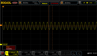
    The attached scope capture is from the RMII clock output (DP83826 pin 19 to be explicit) measured at the eval board J22 pin 22. It's 50 MHz  frequency but I don't have a good sense if this is the expected waveform. It looks pretty much the same on the controller board after the relatively long connecting wires.

    10Mbps configuration seemed to work fine.

    I'd love to have some samples but like many other parts in the world right now there is no availability. Seems to be occupying my life these days on a number of projects!

    I'd appreciate your input on the PHY configuration and if we should be moving back towards the advanced configuration. And also your input on the RMII clock would be useful. Your suggestions have been very valuable.

    Take care - Duncan

    AE-Main DP83826 PHY Evaluation.xlsx

  • Hello Duncan, 

    Thank you for the mail and good to know there has been some progress.

    The clock looks good. Verifying if there is any phase shift near the controller would be good.

    10Mbps configuration seemed to work fine means the connections are correct and working.

    The basic mode should meet your requirement. I do not know the application, if you need low latency you can configure to enhanced mode.

    I am also assuming you have made the wire length optimization.

    Regards,

    Sreenivasa

  • Sreenivasa,

    Attached document shows shortened (1/2" shorter) and direct-soldered wire connection between our board and the EVM adapter. It also shows the reference clock on the EVM RX_CLK net and on our board µC RMII_REF_CLK net. There is some visible phase shift but I'm unable to determine if it's significant or not. What is allowable phase shift for this signal?

    Still configured in basic mode and it seems to be behaving as before. Appreciate any other suggestions you might have.

    Thanks - Duncan

    AE-Main to DP83826EVM Evaluation Update - 210517.pdf

  • Based on the tests till date, the RGMII interface is working. Now it is the speed optimization and will require some additional testing.

    if there are some error check being done by the MAC, can you please ignore them.

    What are you observation at 100 MBPS ? Not working at all 

    For the timing, please refer to below tables 

    7.13 Timing Requirements, RMII Transmit Timing

    7.14 Timing Requirements, RMII Receive Timing

    Regards,

    Sreenivasa 

  • Hello Duncan, 

    DP83822 has 60R series impedance on all the output signals. I see a 33R on the schematics.

    Does the TX signals have series resistors near the host. If yes, can you please match the resistance (~90R and check).

    Thanks

    Sreenivasa

  • Sreenivasa,

    Thanks for the additional guidance. I did check operation at 100M (change Strap1 from externally pulled low to internally pulled high on the EVM) and it did not work. Going back to 10M and it was working again.

    Now I am going to make the series resistor changes you suggested as detailed in the attached document. Needed to order some 0402 parts which should arrive early next week. There are no TX series resistors in the existing design but I can patch them in. I will repeat the 100M test and let you know how it goes.

    I could not find the RMII Transmit/Receive timing tables in the data sheet (Table 7.13 and 7.14 don't exist). Is there another document I should be looking at?

    I know that the MAC is not using the RX_ER signal at this time.AE-Main DP83826 Series Resistor Changes - 210521.pdf

    Appreciate your help - Duncan

  • Hello Duncan, 

    Thank you for the mail.

    For the timing, please reference to table 8.6.

    Let us see if there is some improvement with the resistors added.

    You mentioned 10 M works but 100 M does not work - can you please provide some additional details - it is never working or works with some errors.

    How are you testing ? Would it be possible to do some loopback tests from the host side to check the RMII interface ?

    Regards,

    Sreenivasa

  • Sreenivasa,

    Juggling too many projects right now - my apologies for the delayed response. Hope that you are doing well. If I could get parts, life would be better, but I think that everyone is facing those same challenges.

    I did change the TX & RX series resistors per your recommendations. Bottom-line is that even with those changes the 10M mode still responds to the ping query but no ping response with the 100M configuration.

    The connected PC with the USB LAN adapter does report the 10M configuration and the 100M configuration with the DP83826 Strap 1 changes but no luck pinging with the 100M configuration. I assume this means that the DP83826 is configured correctly for 100M operation.

    Are there are good examples of what the TX & RX signals specified in Table 8.6 should look like? I can make the measurements but don't have the experience to determine what is acceptable or not. Time for me to learn more about Ethernet so anything you can provide will be helpful. Please let me know if there are specific signals/measurements I can send you.

    Appreciate your help - Duncan


  • Hello Duncan, 

    Thank you for the message. 

    Have you tried doing some loop back tests on the DP83826. This should help you understand the device behaviour.

    The Key difference between 10 and 100 M is the speed.

    Do you have provision on the board to make it an MII interface and test?

    Regards,

    Sreenivasa

  • Sreenivasa,

    Unfortunately we do not have any firmware resources available to implement a loop-back test. We have successfully communicated between the modified board with the DP83826 eval board and the host computer Windows application at the 10M speed.

    We do not have a provision to use the MII interface. The microcontroller we are using only supports the RMII interface.

    Based on the 10M success with the less-than-ideal wired in DP83826 we plan to move forward to integrate that device into our next board design update with the expectation that with the correctly design traces & routing we should not have an issue with 100M operation.

    We are starting that board design update now and plan to build 10 boards in the next month or so. Our biggest problem with the PHY at this moment is availability as there are no DP83826 parts available in world-wide distribution or direct from TI. Are you able to help us out with some sample parts for our upcoming 10 unit build?

    Always appreciate your help - Duncan

  • Hello Duncan, 

    Thank you for the mail and the idea looks good.

    I am not sure on supporting the samples although i can check.

    What is the application of the Equipment?

    Regards,

    Sreenivasa 

  • Sreenivasa,

    The application is a medical device used for cardiac pressure monitoring in a catheter lab environment. The pressure monitoring system communicates to a host control/data computer through the Ethernet interface.

    Hope that you can help with some samples - Duncan

    PS - Would you be available for review of our updated design when we change over to the DP83826? That would be very helpful.

  • Hello Duncan, 

    Yes we can support the review. Please let me know when the design is ready. We would need 2-3 days time based on priorities.

    Regards,

    Sreenivasa

  • Sreenivasa,

    Appreciate your willingness to help out with the updated design review process. A key part of us making the change to the DP83826 is going to be getting some samples for our next build. Do you have any update on any samples that you could provide?

    Thanks - Duncan

  • Hello Duncan, 

    Understand.

    I have updated the requirement to the marketing team to take this forward. 

    I am not sure how it works but i assume someone from the sales would look into this.

    Is there an email ID that i can share ?

    Regards,

    Sreenivasa

  • Sreenivasa,

    Contact info below. Thanks.

    Duncan MacGregor

    Tructronics, Inc.

    dmacgreg@tructronics.com

  • Hello Duncan, 

    Noted and Thank you.

    Regards,

    Sreenivasa