This thread has been locked.

If you have a related question, please click the "Ask a related question" button in the top right corner. The newly created question will be automatically linked to this question.

TCAN1042G-Q1: how to measure or calculate the reflection of the CAN bus or differential bus

Part Number: TCAN1042G-Q1

Hi, 

My customer is wondering how to measure the reflection and if there are appnotes discuss about how the calculate or analysis. 

They are now currently using 3 termination in the network but operating ok. 

From my understanding the mainly concern should be the differential voltage cross load and the reflection problem.

Will it be ok to work with 3 termination resistor in the same bus? 

Please let us know if there are concerns to operate in this way, great thanks for your help.

  • Hello,

    There is some laboratory equipment that can support "time domain reflectometry" (TDR) measurements that can be useful in evaluating signal cables. They essentially send a short pulse down the cable and plot the magnitude of the reflected pulses over time. If you don't have such equipment available, you can measure the symbol response of a cable by sending single bits (dominant and recessive) and observing the signal waveforms for reflections. (It can be easier to identify reflections this way if you have some estimate of the delay through the cable and back. If you know the cable velocity then you could use it to compute this, but if you aren't sure then a common assumption is about 5 ns per meter.)

    Using three terminations can be ok, but you should be careful of their value. It is generally best to keep the equivalent resistance between CANH and CANL close to 60 Ohms, since this is the condition for which many of the driver parameters are specified. This is generally accomplished via use of two parallel 120-Ohm resistances, but could also be accomplished via three 180-Ohm resistances. The downside to this is that the terminations may not perfectly match the cable impedance any longer, and reflections (with magnitude dependent on the degree of impedance mismatch) would result.

    Regards,
    Max
  • Hi,

    Currently i use TCAN1042 on three devices which located on the same CAN bus.

    Due to BOM control, i pose three 120 ohm terminal resistors on CAN bus.

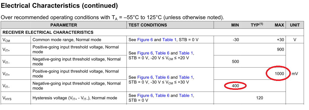
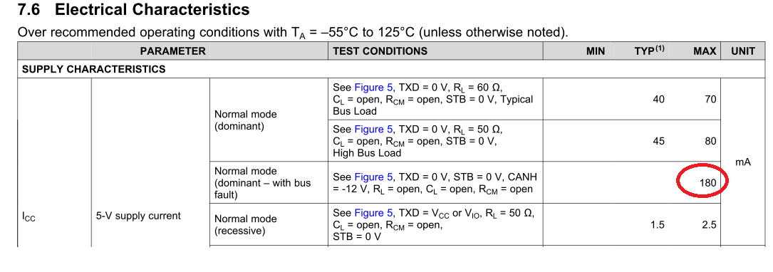
    The measured waveform meet the RX threshold(measured CAN_H-CAN_L:1.92V) (Fig.1) and the driving current(measured 50.4mA)  can under the ICC:180mA(Fig.2).

    The CAN Bus length is under 2m in our application.

    If i have to obey the equivalent resistor value 60ohm or just to meet the TCAN1042 spec. and the reflection phenomenon is not obvious ? 

    Thanks!

    Fig.1 : TCAN1042 receiver spec.

    Fig.2: TCAN1042 ICC maximum  value

  • Zhe,

    The drivers for our CAN transceivers are designed to output the correct CAN levels to a 60Ω load. If your system is able to generate the correct signals over the termination you've chosen, I suppose that is okay, but I can't recommend against a 40Ω termination load on your CAN bus. 

    In order to minimize reflections, the source impedance needs to match the load impedance. Because the drivers are designed to drive over a 60Ω load, to optimally minimize reflections, the load impedance will need to be as close to 60Ω as possible. Ultimately, running tests on the system itself to determine signal integrity is your best bet, but to reduce reflections, matching the source and load impedance is necessary.

    Regards,