This thread has been locked.

If you have a related question, please click the "Ask a related question" button in the top right corner. The newly created question will be automatically linked to this question.

DS90UB914A-Q1: How to Margin Analysis Test

Part Number: DS90UB914A-Q1
Other Parts Discussed in Thread: ALP, USB2ANY

Hi,

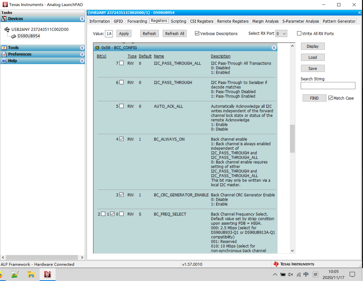
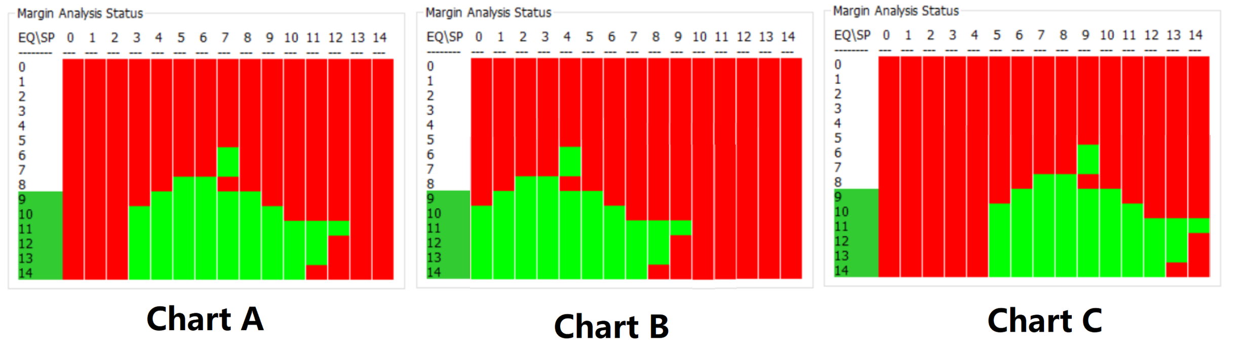
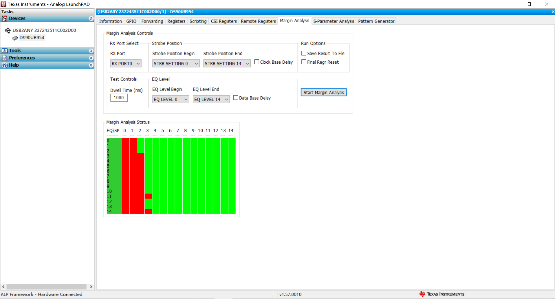
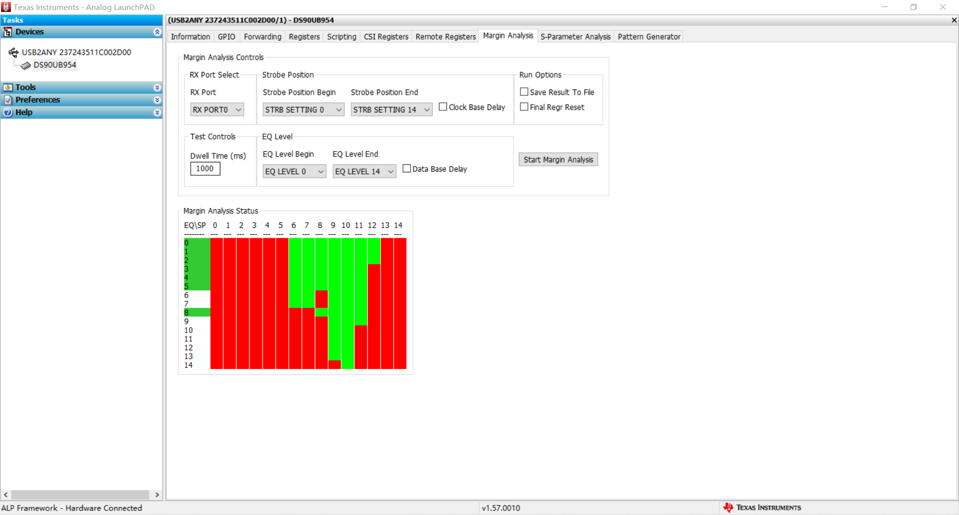
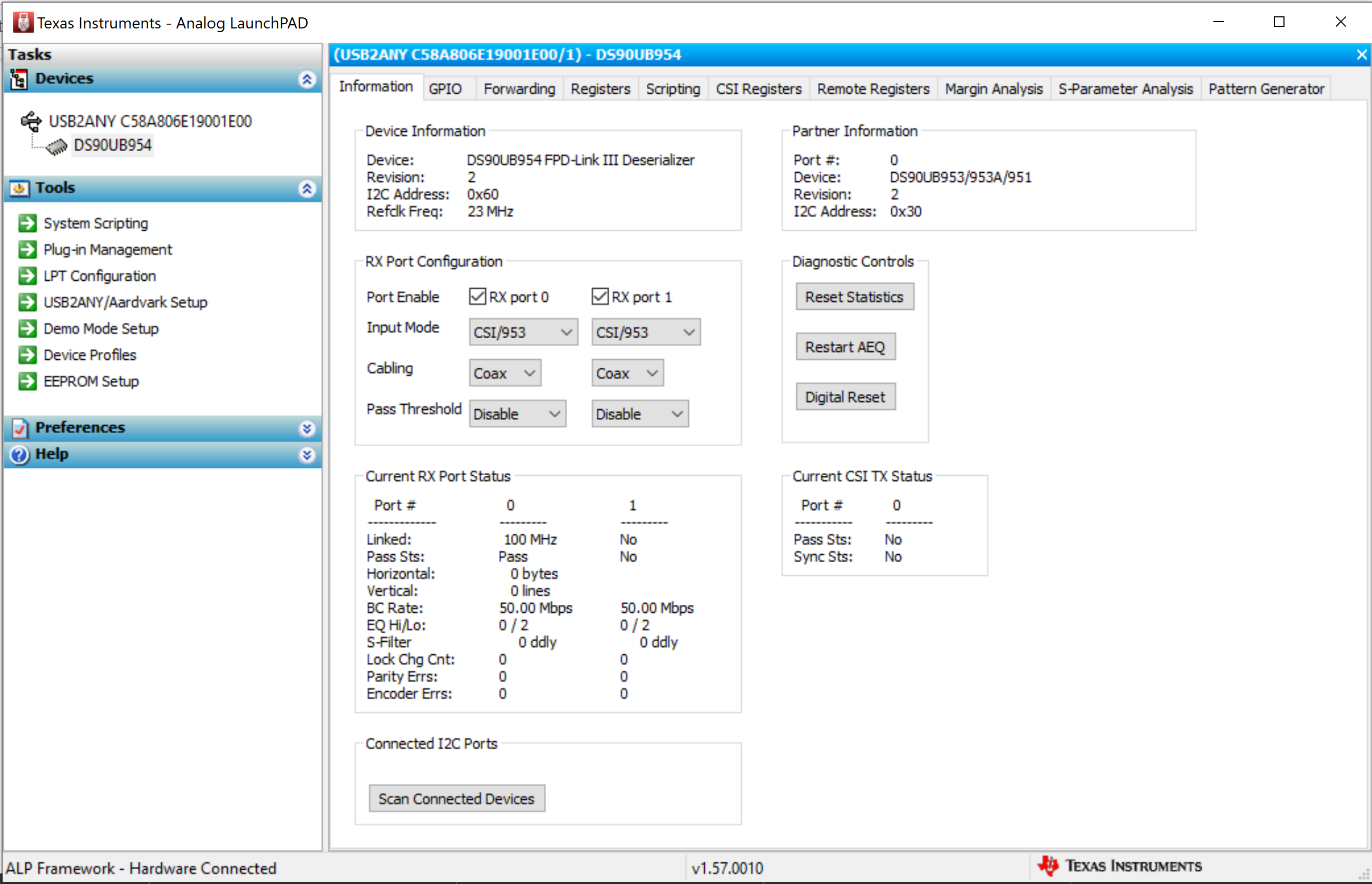
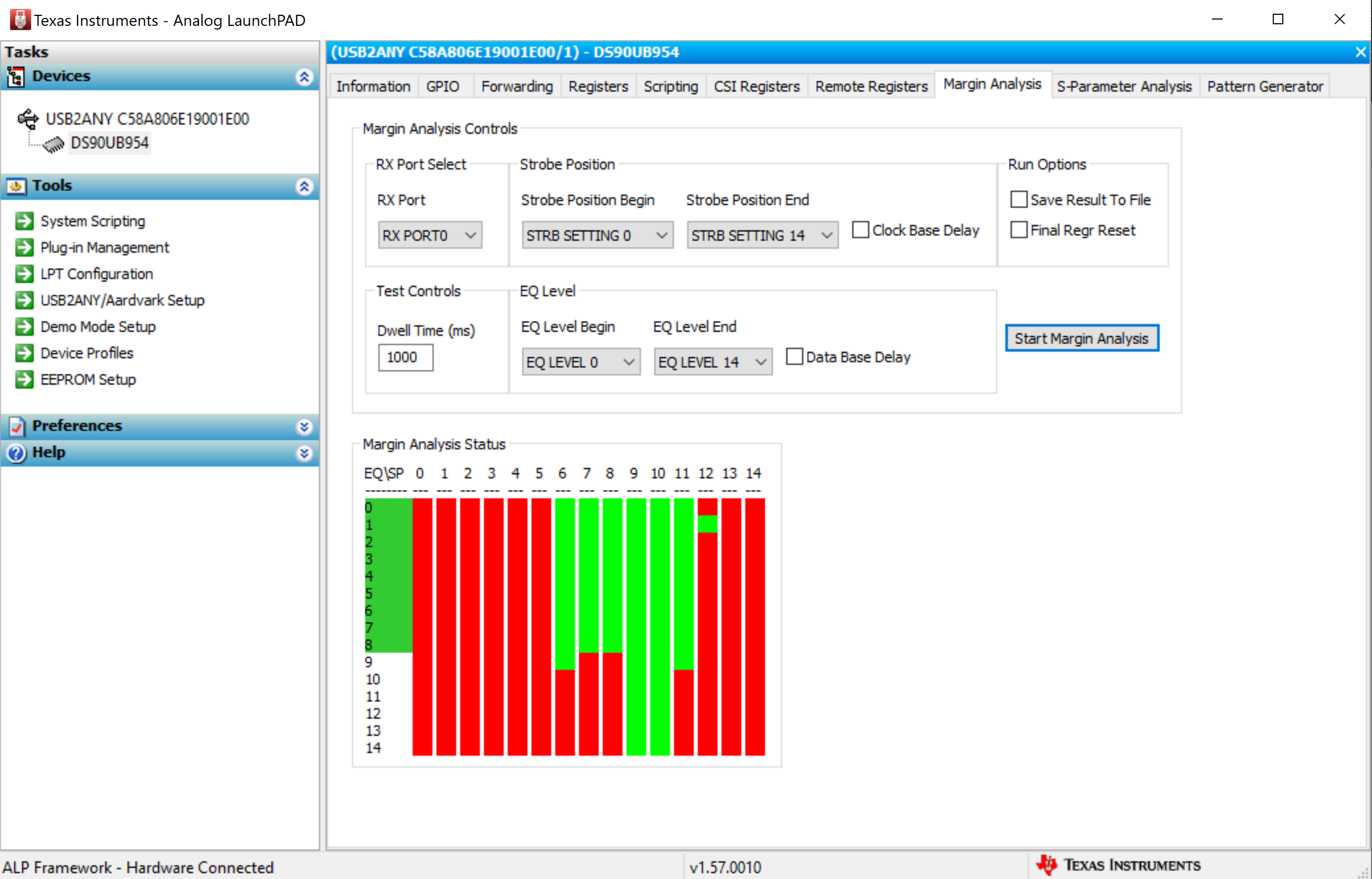
I have image sensor connected to DS90UB913 then via FPD-link III to DS90UB914. DS90UB914 is on my board and I2C lines are accessible. I would like run Margin Analysis Program (MAP) using an Analog LaunchPad software.

I meet a issue is that the ALP can't detect DS90UB914 via USB2ABY adaptor. Could you give some advices?

Background information :

1. I have read USB2ANY Interface Adapter User's Guide(SNAU228–January 2018), SNLA301–January 2019 and SNLU243–January 2019.
2. The ALP software version is v1.57.0010.
3. The USB2ANY adapter hw version is HPA665, firmware version is 2.7.0.0.
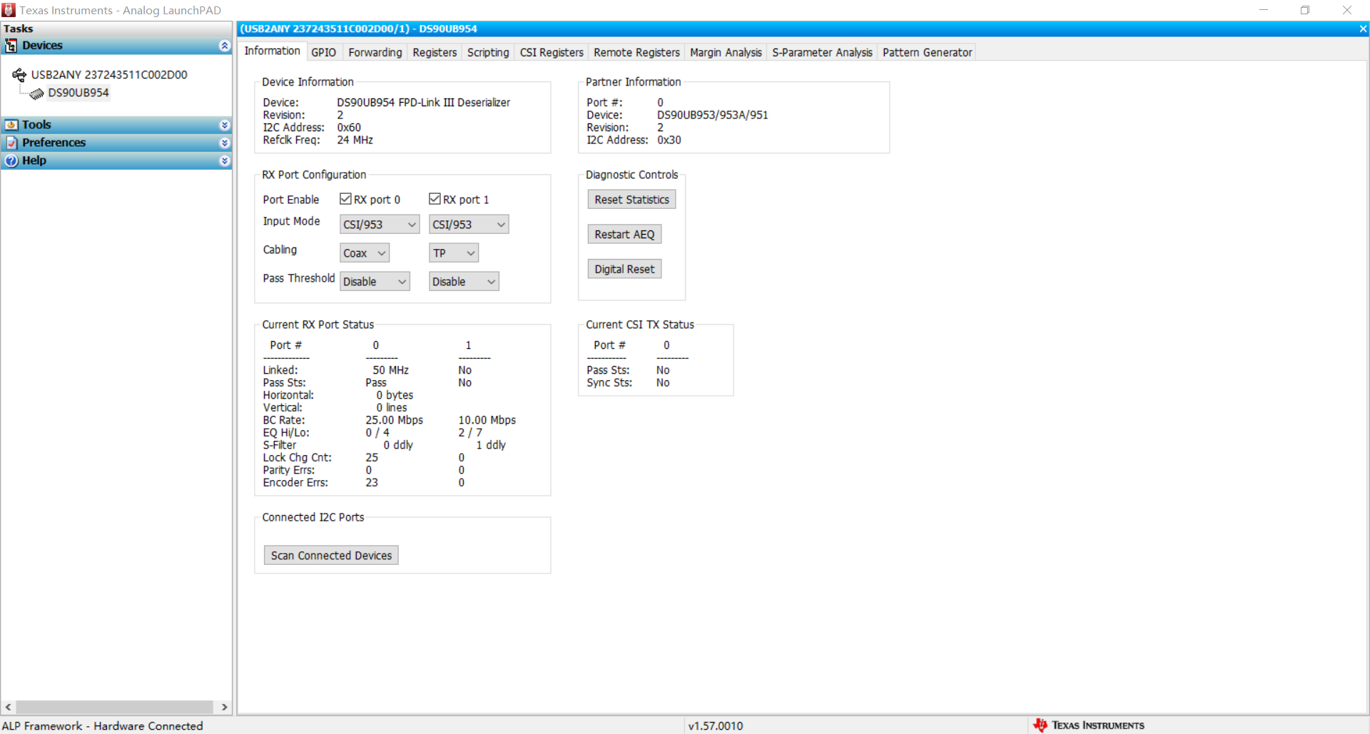
4. The system is:  PC(ALP) --- USB2ANY adaptor(IIC) --- DS90UB914(IIC ID:0xC0)
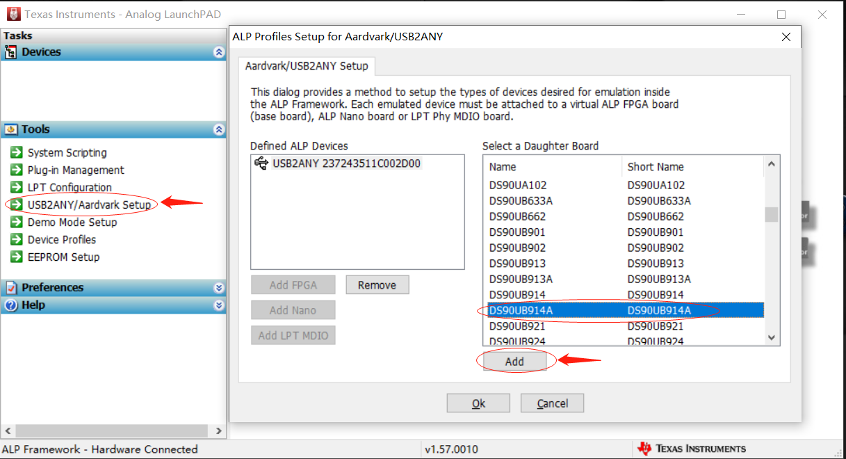
5. add deserdes frofile:

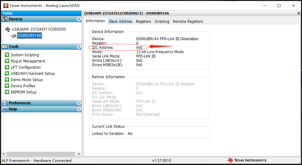
6. The ALP can't find deseredes:

  • 5. add deserdes:

    6. The ALP cant't find deserdes:

    Best Regards,

    Fred

  • Fred,

    a) Could you show under "Help --> About this program"? I want to see the build date to double check you have the latest ALP-PROFILE-UPDATE installed.

    b) Under Slave Address Tab, did you select correct I2C device address and try?

    Thanks,

    Vishy

  • Hello Vishy,

    Now the ALP can detect DeSerdes via USB2ABY adaptor.
    The reason is that I confused the definition of I2C line order of J4 connector on USBANY adaptor.

    About test result, I have read SNLA301–January 2019 and SNLU243–January 2019.


    But I have a queasion, the data in chart is as follow, which is better? Why?

    How to judge? Could you share some spec?


    Thanks,

    Fred


  • Fred,

    I am glad you figured the ALP connection issue.

    Regarding your Margin Analysis result, is this on your 914A platform? We don't support Margin Analysis on this device.

    Can you give us more details your setup and how you are running? Please upload screen shot of ALP info tab and Margin Analysis Tab,

    Thanks,

    Vishy

  • Vishy,
     
    Now I have image sensor connected to DS90UB953 then via FPD-link III to DS90UB954.
    The system is: PC(ALP) --- USB2ANY adaptor(IIC) --- DS90UB954 ---(fakra cable)--- DS90UB953 --- Image sensor
     
    1) ALP info tab:
     
    2) Margin Analysis Tab:
    3) I want to know that if the data in chart is as follow, which is better? how to judge it?
    Thanks,
    Fred 
  • Fred,

    Looking at the info tab "Current RX Port Status" panel, I don't see a valid link. It says linked as "No". It should show instead a valid link status as below


    Also, please check register 0x58 (BCCconfig) as below

    Once you have a valid link please rerun Margin Analysis and let us know.

    Thanks,

    Vishy

  • Hi Vishy,

    1) Only one serdes(DS90UB953) is connected to the Port0 of DeSerdes(DS90UB954), the info tab is as below:

    2) register 0x58 (BCCconfig) as below

    3) Please share some guides about how to judge the test result.

    If the test result in chart is as follow, which is better?

    Thanks,

    Fred

  • Fred,

    The result you show in charts A, B, C looks very different from what I have seen. That's why I am debugging any setup issues. 

    a) Your info tab is now showing 25Mbps but BC_Freq_Select in register 0x58 shows 010 which implies 10Mbps non-synchronous back channel. Could you share a schematic of your 953 mode strap selection? See section 7.4.2 of the 953 data sheet.  Are you using synchronous or non-synchronous mode?

    b) Please explain why you are choosing 25Mbps as the BC rate?

    c) What's the length of your cable?

    d) Between the charts, Chart C looks most possible. 954 DS recommends sfilter config max/min in register 0x41 programmed as 0xA9 and this agrees more with Chart C.

    Thanks,

    Vishy

  • Hi Vishy,

    a) b) I check DS settings, the value of register 0x58 is set 0x5d. I double the register value via ALP. The result is as below:

    c) The length of cable is 5m.

    d) Chart A is test result via ALP. Then Chart B and Chart C is made by chart A shift left or right.

    Suppose there are three results like chart A, chart B and chart C, which chart is better?


    Thanks,

    Fred

  • Fred,

    a) Please clarify if you are using Synchronous or Non-synchronous mode. 

    b) For Margin Analysis test, we suggest to run the link at the highest speed so the link is fully exercised. Can you set the back channel at 50Mbps and so the devices are linked at 100MHz and then try running MAP again?

    c) Better to use result from the tool (A) not shifted versions. I don't get how you are shifting it. What's the reason for shifting?

    Thanks,

    Vishy

  • Vishy,

    a) Please clarify if you are using Synchronous or Non-synchronous mode. 

    ----> I am using Synchronous mode.

    b) For Margin Analysis test, we suggest to run the link at the highest speed so the link is fully exercised. Can you set the back channel at 50Mbps and so the devices are linked at 100MHz and then try running MAP again?

    ----> When I am setting the back channel at 25Mbps, the margin test result is better than the back channel freq is at 50Mbps.

    ① back channel at 25Mbps:


    settins: R[0x58] = 0x5d

    DS90UB954:
    0x60,0x1f,0x02    
    0x60,0x33,0x21    
    0x60,0x20,0x20    
    0x60,0x4c,0x01    
    0x60,0x6d,0x7c    
    0x60,0x58,0x5d    
    0x60,0x5c,0x32    
    0x60,0x5d,0x20    
    0x60,0x65,0x20    
    0x60,0x5e,0xa0    
    0x60,0x66,0xa0    
    DS90UB953:
    0x32,0x02,0x73    
    0x32,0x32,0x49    
    0x32,0x06,0x81    
    0x32,0x07,0x0a    
    0x32,0x39,0x60    
    0x32,0x41,0x60    
    0x32,0x0d,0x0f    
    0x32,0x0e,0xf0

    ② back channel at 50Mbps: R[0x58] = 0x5e


    settins:

    DS90UB954:
    0x60,0x1f,0x02    
    0x60,0x33,0x21    
    0x60,0x20,0x20    
    0x60,0x4c,0x01    
    0x60,0x6d,0x7c    
    0x60,0x58,0x5e    
    0x60,0x5c,0x32    
    0x60,0x5d,0x20    
    0x60,0x65,0x20    
    0x60,0x5e,0xa0    
    0x60,0x66,0xa0    
    DS90UB953:
    0x32,0x02,0x73    
    0x32,0x32,0x49    
    0x32,0x06,0x81    
    0x32,0x07,0x0a    
    0x32,0x39,0x60    
    0x32,0x41,0x60    
    0x32,0x0d,0x0f    
    0x32,0x0e,0xf0

    c) Better to use result from the tool (A) not shifted versions. I don't get how you are shifting it. What's the reason for shifting?

    ----> Suppose there are three test results of chart A, chart B and chart C. Which result is better?


    Thanks,

    Fred

  • Fred,

    I tested ALP Margin Analysis on 954 + 953 EVMs (synchronous mode 50Mbps back channel, 100MHz link)

    a) Result for 3m+2m+0.6m  setup (as I didn't have a 5m cable):

    Above result looks somewhat closer to your 5m cable result (2nd picture in your post above). 

    b) Result for 10m cable

    c) As you can see even for 10m cable, the suggested EQ gain range is 2 to 8 versus your charts A - C where EQ gain range is 9-14 and so they didn't look right to me. Probably you have to review your pcb, cable and channel loss and debug the reason.

    d) Note I am not having any image sensor connected and don't have any CSI forwarding initializations. Suggest you also run Margin Analysis without those initializations and compare. This ensures there's no interference between MA code and your initializations. Device itself to maintain lock sends forward channel test frames. 

    Thanks,

    Vishy

  • Vishy,

    Thanks a lot.

    Fred