


If the USB PD "Power Rules" for PD2.0 rev 1.2 and PD3.0 is a new topic for you, I suggest reading my other 2 posts on the topic before this post:

Instead of solely focusing on DC-DC converters, this post will change direction slightly to AC-DC conversion with variable voltage outputs.
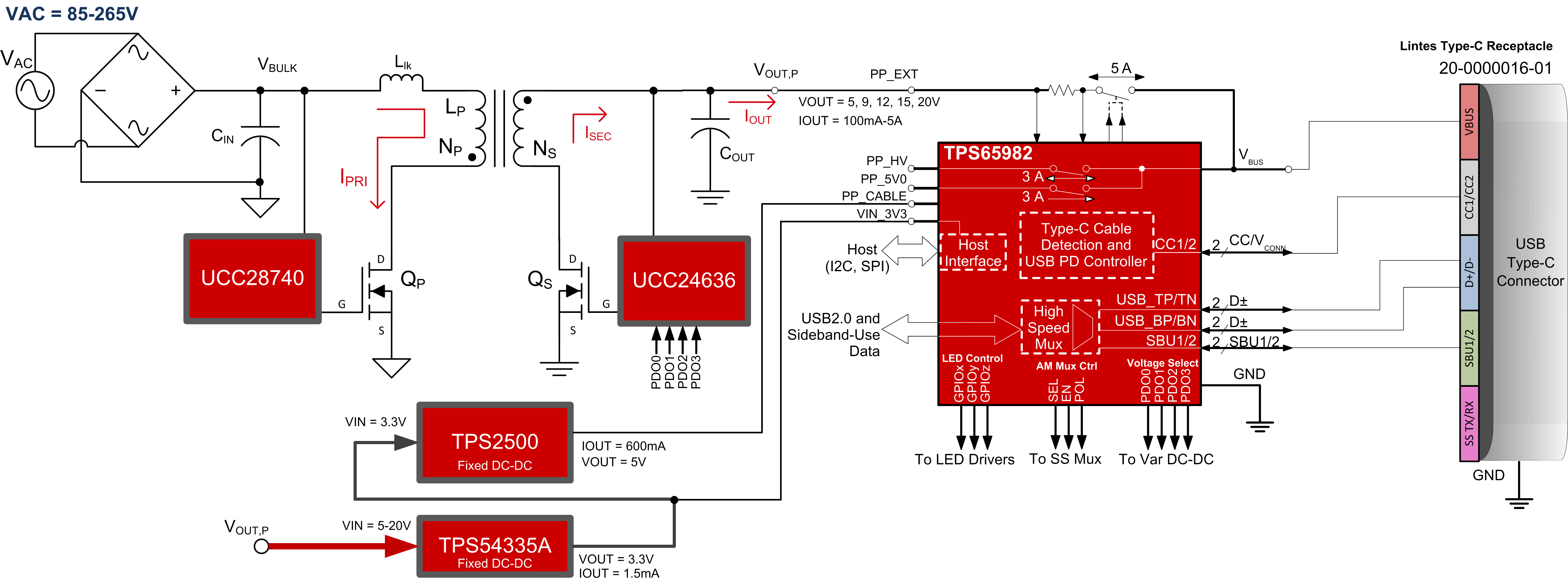
This post will focus on Power Supplies that need to take AC line power as an input and source DC power to VBUS for Type-C & PD. The PMP11451 is a good starting point, but what about designs that need to provide voltages for the new USB PD "Power Rules" at 5, 9, 15, and 20V? What about power supplies that also need to pass data over the Type-C cable? For example, most TVs are powered from AC line power, but could deliver PD power to laptops and tablets while showing video on the TV screen. Similarly, in areas where power-line communication is prevalent, the AC adapter sourcing power may also be a DFP for data.
The following block diagram is a simplified version of the power path in such a circuit, focusing primarily on three ICs: UCC28740, UCC24636, TPS65982.
The portion of the schematic that is modified to allow variable voltage control from GPIOs is shown below. Again, changing a fixed voltage supply to a variable AC-DC supply only requires a modification to the R1/R2 resistive feedback network. In this circuit, since 5V may be the highest DC voltage available, the 5V rail for PP_CABLE is generated using a DC-DC boost converter from the stable 3.3V rail. This optional feature is omitted from the 1-page schematic attached.
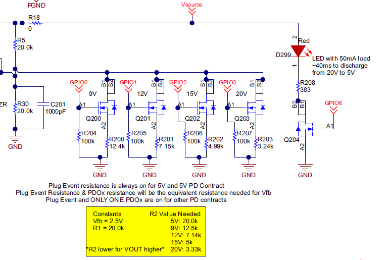
In this circuit, it is easy to see the R1/R2 circuit given that Vfb = 2.5V, and VOUT = 5V is desired by default. Therefore, R1=R2 to generate twice the feedback voltage at the output node. In the schematic, R1 = R5 = 20k and R2 = R30 = 20k, and the R2' resistors in parallel with R2 are as follows:
R2A = R200 = 12.4k for 9V; R2B = R201 = 7.15k for 12V; R2C = R202 = 4.99k for 15V; R2D = R203 = 3.24k for 20V
The full schematic is attached at the end of this post. Most schematic annotations keep the same numbering system from PMP11451, while the TPS65982 Type-C Port Controller components are annotated starting at 200 (for example U200 for ICs, D200 for diodes, R200 for resistors, C200 for capacitors, etc.)
TPS65982_Var-AC-DC-Converter_from_PMP11451_pg1of1.pdf
NOTE: This circuit is guaranteed up to 60 Watts (20V, 3A) and designed for up to 75 Watts. Any power greater than 75 Watts will require Power-Factor Correction (PFC) on the Primary side where the AC power is monitored. 100 Watt designs are outside the scope of this post.

