This thread has been locked.

If you have a related question, please click the "Ask a related question" button in the top right corner. The newly created question will be automatically linked to this question.

ISO1042-Q1: Isolation of the CAN and shifting and correcting the electrical reference

Part Number: ISO1042-Q1
Other Parts Discussed in Thread: ISO1042

Hi 

We are currently facing a technical challenge right now as we use :

- 2 Batteries 12 V in series and 2 DCDC (each DCDC connected to a battery 12V)

- DCDC1 is connected to a 12V batteries : so connected to 0v as GND and 12V

- DCDC2 is connected to 12V of battery number1 and the 12V of battery number 2

As a result the CAN signal going out of the DCDC2 has an offset of 12V,

Therefore, we are looking to a device able to isolate the CAN network and able to shift back the CAN signal to the correct reference (GND); so we remove the 12V offset within the signal,

I was wondering if the device ISO1042-Q1 is:

- able to do that

- suitable for automotive applications

- comes with a socket to allow soldering wires 

Also, what would be the best location for this device in a vehicle ? (like behind glove department I guess)

Thanks,

  • Hi Redouane,

    Thank you for posting, and welcome to E2E!

    Since CAN transmits data using a differential pair, an offset of 12V will not prevent data transmission when using most TI CAN transceivers.  ISO1042-Q1 can withstand up to +/-70V on its CANH and CANL pins, so differential CAN signals with a common mode of 12V are well within recommended operation. ISO1042-Q1 is also an automotive version of ISO1042 that is subjected to additional automotive-specific qualifications and production tests which reduces the DPPM rate over the non-Q1 ISO1042.

    Our devices are not sold with sockets, but we do have evaluation modules available to facilitate bench analysis of our parts. The EVMs for ISO1042 can be found here (ISO1042DWEVM) and here (ISO1042DWVEVM).

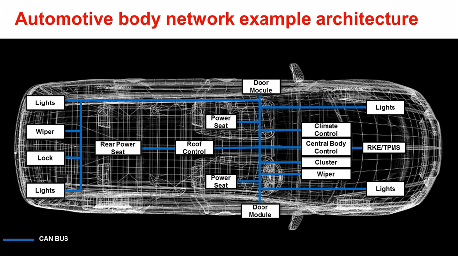
    Our isolated CAN transceivers should be located at each CAN node that requires isolation in a car. If there is some circuitry communicating through CAN behind the glove compartment (for climate control or infotainment, for example), the ISO1042-Q1 can be placed on the PCB between the bus cables and local circuitry. Below is an automotive body example showing some of the typical locations of CAN nodes in an auto and their functions:


    More information on the CAN protocol and its applications can be found in this Automotive interface overview from ti.com. Please let us know if you have any additional questions and if you are interested in ordering an EVM.


    Respectfully,
    Manuel Chavez

  • thanks for the answers, still wondering if the module can come with a casing or something, I am still wondering how to fix it in our vehicle, if you have  pictures of the device in a vehicle that will be perfect,

  • Hi Redouane,

    The EVMs that Manuel Chavez mentioned are only meant for device electrical and switching performance evaluation and hence, come as standard PCBs for testing. As this is not a complete end-application product, it does not come in any casing or enclosure.

    Sorry, we do not have any pictures showing how the device can be mounted in a vehicle as our scope is only limited to IC development and we do not do any testing at vehicle level. The TIer1 companies and OEMs are the right people with knowledge on positioning modules in a vehicle.

    Let us know if you have any further questions, thanks.


    Regards,
    Koteshwar Rao