This thread has been locked.

If you have a related question, please click the "Ask a related question" button in the top right corner. The newly created question will be automatically linked to this question.

ISO1050: Is there a risk of damage when the chip(ISO1050) is subjected to pulse voltage?

Part Number: ISO1050
Other Parts Discussed in Thread: STRIKE, ISO1042, ISOW1044, ISO1044

Hi Teams,

Is there a risk of damage when the chip(ISO1050) is subjected to pulse voltage?The following is a description of this voltage:

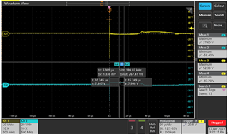
a.The yellow waveform represents CANH to ground, while the blue waveform represents CANL to ground

b.The maximum peak voltage can reach 87V, lasting for about 20 nanoseconds

c.Description of lightning protection testing conditions:

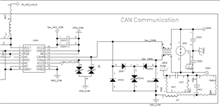
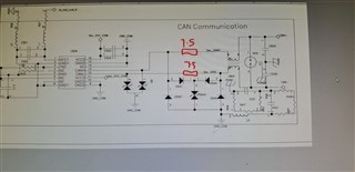
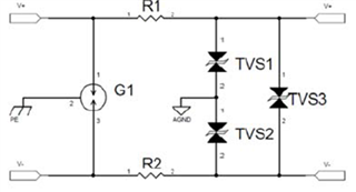
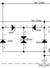
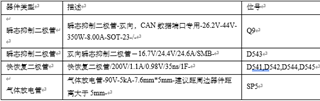
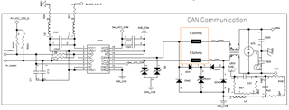
Strike a common mode 3KA lightning current between CAN+ and PGND,Most of the lightning current of this 3KA is discharged from the CAN+ to PGND through a triode discharge tube,This current is decoupled by a common mode inductor, and then a residual voltage is formed at both ends of the TVS. The pulse voltage waveform of the chip pin to ground measured by the oscilloscope is as follows.

d.The voltage limit given in the ISO1050 device specification is -27V to+40V, which should be the result of DC voltage testing. Is there a risk of damage when the chip is subjected to nanosecond voltage exceeding the specified stress?

  • Hi ,

    The ISO1050 device might be able to withstand 87V for 20ns however 3kA lightning current is a bit too high for the device. 
    You have to use necessary protection components to achieve bus protection. Please go through the TIDA-00629 reference design for CAN IEC ESD and surge protection for necessary component ratings.

    Thanks

    Vikas J

  • Hi Vikas Jeevannavar

    Thank you for your reply!

    1. The chip is applied to outdoor power supplies, and its interface requires external wiring, which can withstand a lightning current of 3KA in some harsh environments.This 3KA current will be mostly discharged by the discharge tube(SP5) at the port.

    2. The CAN bus protection is designed in the circuit, and the 87V pulse voltage is obtained by measuring the GND waveform of CANH/CANL after passing through the discharge tube (SP5), common mode inductor (L802), and TVS.

    3. Through the protective circuit above, our company repeated three rounds of lightning tests, and the CAN circuit can still maintain normal communication. However, what we are unsure about is whether this pulse voltage will damage the chip

  • Hi Vikas,

    This is Francis, FAE cover Vertiv.

    Can we draw a definite conclusion whether ISO1050 can be able to withstand 87V for 20ns? (Consider customer's protection circuit.) Or it is out of spec?

    On the other hand, customer add two extra 7.5ohm resistors for releasing current, which is shown as below. Could you please help check whether it is suitable for device? For example, affect the transmission rate, or generate signal reflection.

    Thanks a lot!

    BRs,

    Francis

  • Protection circuit description:

          The natural cooling module has added a lightning strike requirement of 3KA for differential mode/common mode due to the possibility of CAN signals being connected externally. Compared to the original CAN protection circuit, a three terminal discharge tube has been added to the CAN+/CAN external port, forming a typical secondary protection circuit. As follows:


           As mentioned above, the first stage is a three terminal gas discharge tube, which can serve as both differential mode protection and common mode protection. The rear protection circuit uses three bidirectional TVS tubes for differential mode common mode protection, and the two protection circuits use resistance or inductance decoupling to reduce the residual voltage of the rear stage.

           In addition, due to the large body capacitance of the selected differential mode TVS diode reaching the nF level, in order to reduce its impact on the CAN signal, a fast recovery diode bridge with a small body capacitance (tens of pF) was used to connect it in series to avoid affecting the signal transmission rate.

  • Hi Wenhao,

    Thanks for sharing additional information. Since Vikas is currently on travel, I will help you with this discussion in the meantime.

    If I understand your questions correctly, you primarily see the below two transients appear on ISO1050 CAN pins.

    1. A voltage transient of 87V lasting 20ns.
    2. 3kA lightning current between CANH and PGND.

    Voltage transient of 87V lasting 20ns:
    As Vikas stated earlier, we believe the device might be able to withstand this voltage transients but since this is outside device specifications and we do not test the device with such transients, we will not be able to guarantee that the device will withstand it across all units. You would have to incorporate appropriate protection components to make sure such voltage transients get suppressed and the voltage at CAN pins is restricted such that device ratings (+40V/-27V) are not violated. A TVS diode with appropriate thresholds should be sufficient and I see that you are already using TVS diode on CAN pins.

    3kA lightning current between CANH and PGND:
    I am not sure if you meant to say that the 3kA lightning current when passed through all the protection circuit that you have already incorporated creates 87V at 20ns duration, if this is what you mean, please do confirm.
    If my understanding is correct, then we believe the device might be able to withstand this 87V pulse but we cannot guarantee that all units are going to withstand it consistently as we do not test for such transients.

    If 3kA lightning current and 87V @ 20ns tests are two different tests, then I would need your help clarify what voltage does this 3kA lightning current create at CANH and CANL pins of ISO1050. Based on the voltage it creates, I might be able to confirm if this is okay or not.

    I would also like to mention that ISO1050 is one of our older isolated CAN transceivers. Our newer isolated CAN transceivers like ISO1042 offer much higher protection (±70V on CAN bus) and superior overall performance compared to ISO1050, hence, we recommend that you use our newer devices to achieve the best protection and performance.

    Let me know if you have any questions, thanks.


    Regards,
    Koteshwar Rao

  • Hi Koteshwar Rao

    Thank you for your reply!

    1. Your first understanding is correct. When the 3kA lightning current passes through all the protection circuits that have been added, it will eventually generate a voltage of about 20ns (87V) between the chip pins and the ground.Our company will continue to take measures to reduce this stress, and we hope that TI can help test and simulate whether this voltage will cause chip damage if possible

    2. Our company initially used the ISO1042 chip, but due to the need to add alternative models in the future, we changed it to ISO1050

    3. Can you help confirm if connecting two resistors in series (as shown in the figure below) will have an impact on CAN communication, such as whether it will affect the transmission rate and load capacity of CAN? Our actual application may require 5 modules in parallel, that is, five CAN parallel connections

  • Hi Wenhao,

    Thank you for your inputs and confirming the cause for 87V 20ns pulse.

    1. ISO1050 being an older device with lower CAN bus pins rating, it might not be the best device from our portfolio to subject it to 87V. Since ISO1042 already supports 70V on the bus, I can confirm that 87V at 20ns is not going to be a concern.
    2. Thanks for confirming. We recommending choosing newer devices to make sure the performance of your products is in par with the industry. Not sure if you need high isolation ratings, but we do have ISO1044 and ISOW1044 as alternative options which are also our latest devices.
    3. The resistors might not impact much on the timing specifications directly but they might slightly reduce the signal voltage on the bus. This could mean slightly shorter communication length but I believe resistance upto 10Ω shouldn't be of a major concern.
      1. I would recommend sufficiently testing your product with cable length and number of nodes that you expect the product to be used at. If the signal integrity, datarate and other performance specifications are meeting your requirements then you can go ahead with this approach.


    Regards,
    Koteshwar Rao