This thread has been locked.

If you have a related question, please click the "Ask a related question" button in the top right corner. The newly created question will be automatically linked to this question.

SN6507-Q1: SN6507 light load conditions

Part Number: SN6507-Q1
Other Parts Discussed in Thread: SN6507, SN6501, SN6505B

Hi,

I have designed an isolated PSU based on SN6507 just to step up +5V to +12V.

The SN6507 is configured as follows:

Slew Rate:218 V/us 
fCLK:575KHz 
Current Limit - 1.2A 
DC pin N.C - sets duty cycle to default 48%
Soft Start set to 9ms

The SN6507 connects to a pulsed transformer( ratio 3:8 ;  primary inductance of 300uH; Vit= 11V/uS) and rectifier diodes MBR0580S1-7. Also have snubbers at the secundary.

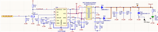
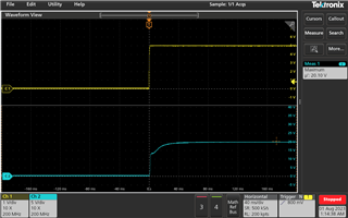
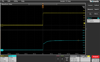
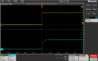
The load is a TI device with an internal LDO regulator. I have seen the output rail that powers this device to be 14.4V when the device is operating. This is slightly higher than expected (it should around 13.3V, the 5V input is very accurate). However, when this device is in sleep mode it only draws 100uA, when this is the case I see the rail going up to ~24V.

Is this a saturation of the transformer ? is it caused by virtually no current drawn by the load?

I have added a zener to clamp the rail , but I do not want to rely on that only, and at the same time I was a simple and cheap solution. Should I add a pre load, to ensure a min current is always drawn say 1mA, would that help the SN 6507? Datasheet does not provide much guidance?

Thanks in advance 

  • Hi Roberto,

    Thank you for reaching out and for providing detailed information regarding the issue you are facing.
    Could you please help me with the schematic and transformer datasheet so that I can make sure there are no issues in the design?

    Considering the conduction losses in device, transformer and across the diodes, the output should be about 12.5V for a transformer with 3:8 transformer with an input of 5V. But if you are seeing higher output voltage (like 14.4V) than it might be possible that the turns-ratio is slightly higher. Seeing 24V is not expected in any situation, please share the transformer datasheet so that I can take a look at it. It would also help if you can share the output voltage waveform showing these behaviors.

    The device doesn't control the output directly, it simply switches the transformer. The load does drop output voltage a little bit and when there is no load, the output is expected to be slightly higher (like 10-20% than average load) but shouldn't be twice the output.

    Is this a saturation of the transformer ? is it caused by virtually no current drawn by the load?

    Saturation leads to a drop output voltage and leads excessive input current, this shouldn't be saturation. No load shouldn't cause any operational issues, the output voltage shouldn't increase so high.

    Should I add a pre load, to ensure a min current is always drawn say 1mA, would that help the SN 6507?

    You shouldn't need a minimum load for the solution to operate normal, please share the requested information to review.

    Datasheet does not provide much guidance?

    I understand your concern, since the device doesn't control the output directly and is largely dependent on the transformer, you might not find more information in this regard in datasheet. Sorry about that.

    I will look forward for the information from you, thanks.


    Regards,
    Koteshwar Rao

  • Koteshwar- thanks for your reply and apologies for the delay-  please see schematic snippet below

  • Transformer datasheet:

    HCTSM8 Series High Clearance and Creepage Distance Transformers (ihs.com)

    Any feedback that could lead to understand why I am seeing this would be appreciated. Thanks again

  • Hi Roberto,

    Thanks for sharing the schematic and transformer datasheet for review.

    The schematic looks fine and I don't see any major concerns with it. The transformer is also designed to work with SN650x devices and we have many customers using them without any issues. Could you please help me with below information to further debug the issue?

    1. Can you please confirm if you have only tested one board with one transformer or multiple boards and multiple transformers?
      1. If it is only one board or one transformer, could you please test another and confirm if you see the same issue?
      2. I am trying to rule out any issues related to one particular board, transformer or test setup.
    2. Can you please help me with power up waveform of output with and without load showing normal output and high output voltages?
    3. Can you please adjust the switching frequency to 420kHz and retest the board?
      1. Since the transformer datasheet refer to SN6501 and SN6505B which operate at 420kHz default frequency, it maybe worth testing under same test frequency to check if that still shows the issue.

    Please help us with the requested information to further debug the issue, thanks.


    Regards,
    Koteshwar Rao

  • Hi Roberto,

    I didn't hear back from you in a while, I am hoping that you were able to resolve the issue. If it isn't resolved, please do help us with the requested information to debug the issue further, thanks.


    Regards,
    Koteshwar Rao

  • Thanks for the follow up email and apologies Koteshwar, I have been busy.

    I have input for your 1.- I have seen the same behaviour in the 3 boards I have tested. I will try .2 and .3 asap. and come back with the info.

    Thanks again

  • Hi Koteshwar,

    Apologies for the delay but I have been busy-I managed to do some measurements: I am plotting the input 5V (yellow trace) at the Vcc pin, and the output of the driver, voltage across TP2 and TP3 with the zener removed- and with virtually no current load.

    Unfortunately adjusting the frequency down to 400KHz has not improved- 

    Fig 1: Fsw_400khz_30K_Rclk

    Fig 2: Fsw_300khz_43K_Rclk

    Fig 3: fsw_200khz_60K_Rclk

    Fig 4: Fsw_105khz_110K_Rclk.png

  • Also I tried the other way around- 1MHz and the behaviour does not change much with respect to approx 500KHz with the 20K resistor.. please see below

  • Hi Roberto,

    Thanks for sharing the waveform. I am surprised to see that the output voltage is steadily around 20V which we do not expect from a transformer that has a turns ratio of 3:8 when the input voltage is 5V. Can you please confirm if the voltage goes down and how much it goes down when you add a load?


    Regards,
    Koteshwar Rao