This thread has been locked.

If you have a related question, please click the "Ask a related question" button in the top right corner. The newly created question will be automatically linked to this question.

ISOW7842: VISO Latch-up issue

Part Number: ISOW7842

Hi,

In our design using ISOW7842, we are facing exactly the same behaviour of the "VISO latch-up" as described in this thread: https://e2e.ti.com/support/isolation-group/isolation/f/isolation-forum/769224/isow7842-latch-up

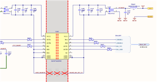
Please find below the schematic. We are using this circuit 3x in parallel, supplied by one TI PMIC TPS65381.

VCC = 3V3 and VISO = 3V3

At startup sometimes VISO goes to >6V, a noise frequency is clearly audible and the component starts heating. It happens 90% on the same component, but it can happen rarely on another of the 3 we have in parallel.

Please find below a print screen of a bad starti with

- 3V3 VCC in yellow

- 3V3 VISO in green

- Current on 3V3 VCC input in Blue

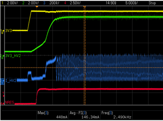
The load on ISO side is about 25mA.

The recommendation that can be found in this forum and in previous datasheets is to add a bigger capacitance on VCC side of around 100uF. We can see that along the years that this recommendation has been removed from datasheet revision F. Could you explain why?

Do you have any idea of what are the causes of this problem?

Thx,

Pierrick

  • Hi Pierrick,

    Sorry to hear that you are facing an issue with ISOW7842.

    We are using this circuit 3x in parallel, supplied by one TI PMIC TPS65381.

    Could you please elaborate what exactly did you mean by 3x in parallel?
    Did you mean 3 ISOW7842 devices used to generate 3 independent 3.3V outputs or are these 3 outputs connected together directly or indirectly?
    Please do share the schematic showing all 3 ISOW7842 devices and their connections to each other, if they are connected.

    It would also help if you could show a clear picture of device samples to read their top marking.

    At startup sometimes VISO goes to >6V, a noise frequency is clearly audible and the component starts heating.

    This can happen if the device schematic and PCB guidelines are not completely followed and only happens on very old samples of ISOW7842. I confirm the year/month of samples based on their top marking once you share the same.

    The recommendation that can be found in this forum and in previous datasheets is to add a bigger capacitance on VCC side of around 100uF. We can see that along the years that this recommendation has been removed from datasheet revision F. Could you explain why?

    The older samples needed this capacitance while the newer samples do not require, this is why the datasheet has been updated.

    Do you have any idea of what are the causes of this problem?

    Please share the requested information to better understand the cause for the problem and I will be able to explain better, thanks.


    Regards,
    Koteshwar Rao

  • Hi Koteshwar Rao,

    PMIC supplies 3x ISOW7842 circuits with 3V3, and each ISOW7842 makes its own independent 3V3_ISO. Outputs are independent and not connected together at all. The schematic picture we posted earlier shows only one channel, but the other channels are identical being fed by the same 3v3 bus.

    Layout Guidelines have been followed according to the new revision of the datasheet (without the 100uF cap)

    Please find below 4x differents marking from 4x different boards. The 3x ISOW7842 that are populated on one individual board come always from the same batch (they have the same markings) for every board. But the boards themselves are not coming from the same production batch.

    The two first marking come from 2x boards we observed the issue. The two others come from boards that we don't know if the issue occurs or not.

    Faulty Board#1: 03AKJ9T

    Faulty Board#2: 03AKJ9T Same Number

    Unknown Board#1: 23CJFNT

    Unknown Board#2: 28CLQKT

    How can we interpret these markings? And how can we identify when a component might be faulty? We have other boards on the field that could have the same issue.

    Thx,

    Pierrick

  • Hi Pierrick,

    Thank you for sharing additional information, this is helpful.

    PMIC supplies 3x ISOW7842 circuits with 3V3, and each ISOW7842 makes its own independent 3V3_ISO. Outputs are independent and not connected together at all. The schematic picture we posted earlier shows only one channel, but the other channels are identical being fed by the same 3v3 bus.

    Understood, thanks.

    How can we interpret these markings? And how can we identify when a component might be faulty?

    The document at the link below explains how to read the 7 character Lot Trace Code (LTC). As it explains, the first character is the last digit of the year it is manufactured (i.e., 0 for 2020 and 2 for 2022) and the second digit the month it is manufactured in (1 is January, 9 is September, A is October, B is November and C is December).

    /cfs-file/__key/communityserver-discussions-components-files/1013/How-to-identify-STC-_2600_-LTC.PDF

    Faulty Board#1: 03AKJ9T

    From the top marking of devices from the faulty boards, I can see that they are from March 2020. The devices from 2020 and before require the 100µF guideline and 2 other guidelines to be followed. Not following these could cause overvoltage issue if the application is noisy. For most applications, we had not seen any customer have any concerns with device while very rarely, some applications required these guidelines to be followed to make sure the noise doesn't affect the device.

    Devices manufactured from 2021 onwards do not need to include the 100µF capacitor at supply input. The LTC from unknown boards indicates that they are from March and August 2022 and hence, shouldn't require the 100µF capacitor at supply input.

    We have other boards on the field that could have the same issue.

    As mentioned, it shouldn't have any issues if the application is not noisy but I cannot guarantee that if the guidelines from older datasheet are not followed. If you haven't seen any issues in the field so far, then I wouldn't expect them to have any in the future as well.

    Let me know if you have any other questions, thanks.


    Regards,
    Koteshwar Rao