


Hi, TI expert
The customer has been experiencing ongoing defects occurrences with the ISO1050.
They are inquiring about the reasons behind these defects occurrence.
[Failure phenomenon]
- Output failure occurs due to a defect in ISO1050, which receives 5Vdc power and supplies 3.3Vdc output.
- VCC1 (1Pin) - GND1 (4Pin) resistance measurement result (measured as a single item after separation from the board)
1) Defective part: Measured at 12 ohms.
2) Normal part: Measured at approximately 600 ohms.
Customer submitted several applications through TI_Customer Returns, but progress through parts analysis was rejected, and only a brief response was received as follows.
→ "Based on customer failure mode “Pin1 (VCC1) low resistance (12Ohm) to Pin4 (GND1) is signature of EIPD/EOS."
Based on the above, the customer has an inquiry as follows.
1. ISO1050DUBR defective factor inspection request
-. Is it possible to determine the cause of a defect?
2. Request for ISO1050DUBR VCC1 single limit test data
-. The VCC1 MAX voltage is 6V. Could you provide data on the phenomenon and type of defects that occur when the voltage exceeds a certain amount of V?
3. Are there any problems with the circuit?
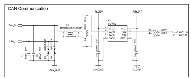
QEM-CCR-2403-00545_TI Quality Report.pdf
Please check. Thank you.
