UCC20225: Feasibility of Using UCC20225 for LM5106 Chipset in DC-MOTOR FULL-BRIDGE Application

Part Number: UCC20225
Other Parts Discussed in Thread: LM5106,

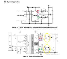
We are using the LM5106 chipset as a DC-MOTOR FULL-BRIDGE.

However, due to poor EMI (RE) characteristics,

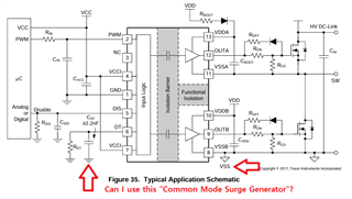
we are considering the isolated type UCC20225.

Is this application not feasible?

Because,

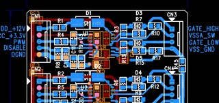
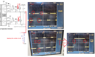
as shown in the diagram below, excessive heating caused resistor damage.

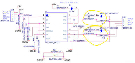
We are reconsidering whether this application is feasible.

Could you provide any insights on this matter?

Thank you.

  • Hi,

    At first glance nothing stands out that would prevent this driver from working in this application. This a typical schematic configuration of the isolated gate driver. Low side channel B is connected to the 12V power supply rail while the high side is being powered with a bootstrap supply.

    Gate resistors getting damaged points towards high heat dissipation through them. I have a couple questions to understand the issue better:

    • Does this happen during any conditions normal operation(such as low voltage test when the gate driver is only switching the MOSFET without any high voltage applied to the power stage) or is it happening during a specific qualification test(such as any high voltage operation test)?
    • Are only the external gate resistors getting damaged or is the gate driver also getting damaged?
      • The internal pull up and pull down MOSFETs of the gate driver will also experience some heating due to switching losses
    • Are you able to share the part number of MOSFETs you are driving?
    • What is your switching frequency?

    Best regards,

    Andy Robles

  • Thank you for your kind response, Andy Robles.
    1. When PWM (16.4kHz) is applied, the resistors heat up.

     Naturally, this occurs while OUTA and OUTB outputs are connected to the gates of the MOSFETs.

    2. The gate driver hasn't been damaged.

    But, though the exact cause is uncertain, I replaced the MOSFETs for the high side and low side as they were faulty.

    3. The part number of the MOSFETs I'm using is NVMFS5C628NL.

    If you could advise on possible causes that can be speculated,
    I will seriously try them out.

    Thank you.

  • Hi,

    This is a slow switching frequency. I would not expect to see overheating on the resistors or on the gate driver with the application conditions.

    • Does this happen every time you operate the gate driver (it can be replicated all the time)?
    • Do you have multiple gate drivers on the system and they all show the issue?
    • Have you tested more than one of your systems?

    Best regards,

    Andy Robles

  • Dear.

    After deeply contemplating the points you mentioned, I have a question.

    Currently, the power configuration of the board has a common ground (GND).

    The voltages are +3.3V, +12V, and +28V (for external MOSFET).

    I wonder if there would be any issues if GND and VSS are connected in common?

    In my experience, even when tying GND together, heat dissipation issues persist.

    If not, should I completely isolate the power using a chipset similar to SN6505?

    Looking forward to your response.

    Thanks.

  • Hi,

    When driving a half bridge you can connect GND from the low voltage side with VSSB if channel B is used to drive the low side.

    Channel A voltage supply would need to be an isolated supply if driving the high MOSFET, but based on your schematic you are using a bootstrap supply which is a valid isolated supply for the gate driver.

    This shouldn't be causing an issue.

    I could offer to do a layout review of the board to see if I notice anything that could be causing the issue. Screenshot of all the layers of the gate driver portion should be sufficient.

    Lastly please reply to the last questions in my last post for better understanding of the issue:

    • Does this happen every time you operate the gate driver (it can be replicated all the time)?
    • Do you have multiple gate drivers on the system and they all show the issue?
    • Have you tested more than one of your systems?

    Best regards,

    Andy Robles

  • Thank you for your answer.

    I will reply below:

    1. That's right. This always occurs whenever the PWM signal and DISABLE (LOW) signal are applied to the GATE DRIVER.
    2. That's right. There are 4 GATE DRIVERs installed. They all exhibit the same issue.
    3. Currently, we have only checked one system.

    Below is the layout of the board. 

    The picture size is too small, so I don't know if you can see it clearly.

    I couldn't find where the mistake was.

    I hope you see something I didn't see.

    Thanks for your reply.