This thread has been locked.

If you have a related question, please click the "Ask a related question" button in the top right corner. The newly created question will be automatically linked to this question.

ISO1042: VDD2 rating

Part Number: ISO1042

Tool/software:

Hi

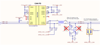
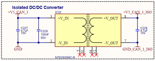
I have an ISO1042 circuit that I can't get to transmit or receive any CAN messages. It's a copy from a reference design so I'm a bit confused! One issue I see is that we are using NTE0505MC-B transformers to isolate the +5V and GND, and are seeing 5.67V on the output of this, which is higher than the max recommended for VDD2 according to the datasheet.  Could this be the reason for the transceiver not working?

  • Hi Martin,

    Thank you for reaching out. 

    Today is a holiday in the US. Please allow us to get back to you on Friday. Thanks.

    Regards,
    Koteshwar Rao

  • Up to 6 V will not damage the device.

    Is the transformer output regulated? If not, then it might be possible to rise further during power up or load changes; check with an oscilloscope. In that case, an LDO might help.

  • Hello Martin, 

    Can you share a system connection diagram? Or is this a TI reference design that you can point me to? 

    I would say its unlikely that 5.67V would cause the device to completely stop working. It would be good to check that the VDD is staying within the maximum range during startup to ensure the device is not getting damaged. If you reduce the voltage, does the device begin transmitting data?

    Best,
    Michael

  • Hi, and thanks for the replies.

    The circuit is below.  The nature of the board means the transceiver is not as close to the connector as we would like.  This is the second iteration and we included the caps and choke to reduce some noise, which it has done.  

    We have not been able to get any transmission through the transceiver in either direction.  Whenever we send the link goes down.

    I also have verified we don't seem to be exceeding 6V at any point on VDD2

  • Hi Martin,

    Thank you for sharing the schematic. I don't see any concerns in the schematic, perhaps there maybe some other concerns elsewhere in the PCB.

    To isolate the issue to ISO1042, can you please apply a signal from a function generator to only TXD and monitor CANH/CANL lines? While doing this, you would have to disconnect the TXD pin from MCU and preferably, other nodes on the CAN bus. This is the best way to find out if the device was already damaged due to other factors or if it is working.

    Let me know if you have any questions, thanks.


    Regards,
    Koteshwar Rao

  • I have setup a test without the SoM attached, so nothing connected to the Tx line.  When I inject a 50kHz (and 125kHz) signal on the Tx pin there is no change on the CAN side of the transceiver. CANL and CAH remain at VDD2.

    Should I be looking to get some new parts?

  • Hello Martin,

    Yes, at this point we would recommend doing an A-B-A swap. Take the unit that is non-functional and place a new unit on the board. If the board works, return the bad unit to the board and confirm that the failure follows the unit. 

    Best,
    Andrew

  • New parts work!

    I also ordered a dev kit to test my setup, and as that was the ISO1042x I ordered that version of parts.  We had the 'B' version on the board originally.  Could this have caused a problem?  

  • Hello Martin, 

    The 'B' version signifies "Basic Isolation". The lower isolation voltage is the only difference and is likely not the cause of your issue based on the problem description. 

    It is more likely that the original device was damaged during testing in some way. The schematic still doesn't suggest any issues that would cause immediate failure of the device (no absolute maximum conditions are exceeded).

    Please continue testing and let us know if you continue to experience issues, or if a failure happens while testing an edge case scenario.  

    Best,
    Andrew