Other Parts Discussed in Thread: TIDA-00892
Dear,
we first time use ISO1432B to replace SP339E and we need double confirm schematic as below:
ISO1432_schematic_review 20190626.pdf
If any suggestion, Please advise me.
Thanks,
Best regards.
Lawrence.
This thread has been locked.
If you have a related question, please click the "Ask a related question" button in the top right corner. The newly created question will be automatically linked to this question.
Dear,
we first time use ISO1432B to replace SP339E and we need double confirm schematic as below:
ISO1432_schematic_review 20190626.pdf
If any suggestion, Please advise me.
Thanks,
Best regards.
Lawrence.
Hi Lawrence,
Thank you for posting to E2E! Regarding this schematic, I have the following questions:
1) What is the purpose of ferrite bead FB6?
2) What is the characteristic impedance of the TX and RX cables connected to the ISO1432?
Thank you,
Manuel Chavez
Hi, Manuel Chavez
1) What is the purpose of ferrite bead FB6?
Lawrence: FB6 will DNE(Does Not Exist), for debug
2) What is the characteristic impedance of the TX and RX cables connected to the ISO1432?
Lawrence: we reference TIDA-00892, about 120ohm connect TX+- and RX+- , have any concern?
If any suggestion, Please advise me.
Thanks,
Best regards,
Lawrence.
Hi Lawrence,
The 120Ω termination resistors are okay as long as the impedance of the cable used to transmit the TX and RX +/- signals is also 120Ω. The termination and cable impedances should match.
I have two more comments about the schematic:


These are my only remaining concerns in this schematic; please let me know what you think!
Respectfully,
Manuel Chavez
Hi, Manuel Chavez
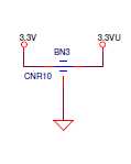
The BN3 (CNR10) is the EMI Suppression Filters(Three-Terminal Capacitor) of MARUWA.
It is for the independent power of the ISO1432B.
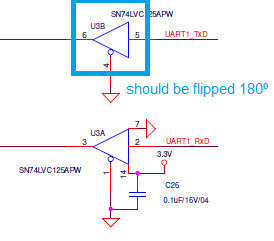
The U3A/U3B are for LED only, not for the data, so I think it is ok!
The LED is connected by the CON3.
About the 120Ω termination resistors, it seems to be not more than 2 pcs in the bus topology.
-> So you mean the IS1432B is the host device , is it right?
If it is right , we should add the 120Ω termination resistors in the schematic.
By the way, the size “0402” of the termination resistors is the common size for RS485? (or the other size it should be?)
The limitation will come from the RS-485 network is 32 or 255 ?
We design the power of the ISO1432B is 3.3V/0.6A. How the decide the power supply capacity?
If any, Please advise me.
Thanks,
Best regards,
Lawrence.
Lawrence,
http://www.ti.com/lit/an/snla049b/snla049b.pdf
The bus termination resistors should only be placed at the ends of the bus as depicted in the figure above. Personally I would recommend using a resistor package size of 0603 or larger for increased power ratings and reliability.
The ISO1432 can drive 256 1/8 Unit Loads. You can see the current consumption levels based on data rate and bus loading from sections 8.11 and 8.12 of the datasheet. You will need to evaluate this based on your system's conditions and sum the total current consumed from all the devices on your RS-485 bus line.
Respectfully,
Lucas
Hi Lawrence,
Please see the comments from my colleague, Lucas, above. We are both on the Isolation team, and isolated RS-485 interface devices, like the ISO1432, are his area of expertise.
I apologize for the delayed response.
Thank you for your patience,
Manuel Chavez