


Hi,
UC1825 and UC1825A has below functions.
UC1825: Dual Totem Pole Outputs (Alternating) - Duty Cycle Range (%80max) - Dead-Time Control by Ct pin.
UC1825A: Dual Totem Pole Outputs (Alternating) - Duty Cycle Range (%50max) - Maximum-duty cycle control upto (%100max) (!but used for VMC!)
My questions are as below,
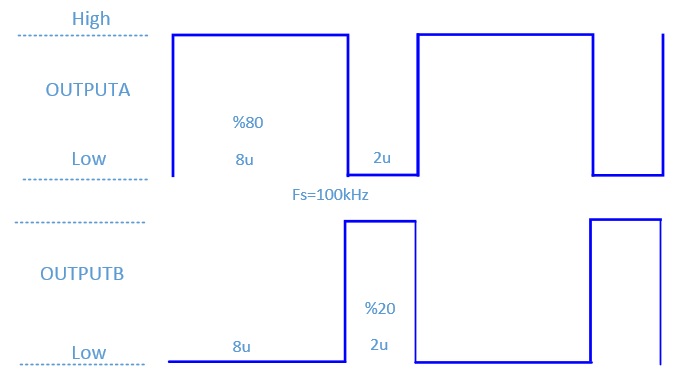
1) For UC1825 - If I set internal oscillator frequency to 100kHz and get the UC1825 worked as a 100V input 80V output buck converter,which means %80 duty. How will be the OUTPUTA and OUTPUTB waveforms? Is it will be as figure below?
Figure-1
 OR
OR
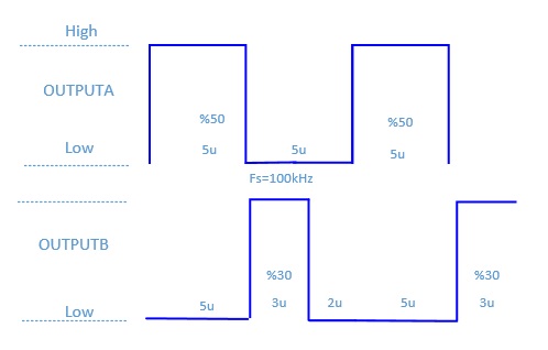
Figure-2
 OR
OR
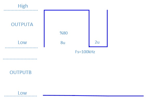
Figure-3
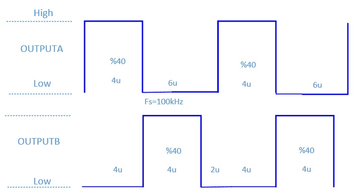
1) For UC1825A - If I set internal oscillator frequency to 100kHz and get the UC1825A worked as a 100V input 80V output buck converter,which means %80 duty. How will be the OUTPUTA and OUTPUTB waveforms? Is it will be as figure below?
Figure-4
 OR
OR
Figure-5
Thanks
