This thread has been locked.

If you have a related question, please click the "Ask a related question" button in the top right corner. The newly created question will be automatically linked to this question.

LSF0108: Looking for good IC selection to send PWM signals to motors. LSF doesn't seem to be working.

Part Number: LSF0108
Other Parts Discussed in Thread: PCF8575, SN74AHCT125, SN74AHC1G125, SN74HCS245, SN74AHCT245, SN74LXC8T245, SN74HCS595, SN74AHCT595

Hello,

I am using LSF0108 and PCF8575 to generate PWM signals and toggle control signals respectively for my motors (step and direction signals) over 2 meter long wires.

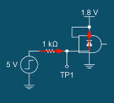
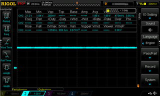
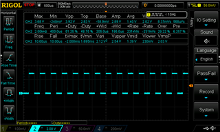
I realize that LSF0108 can convert PWM signals to 5V but as soon as I connect motor control signals they get clamped to around 2.5V. May be that is because LSF0108 and PCF8575 can't supply to load.

I tried searching for answer. Found few options here https://e2e.ti.com/support/logic-group/logic/f/logic-forum/929326/looking-for-an-ic-that-will-convert-3-3v-pwm-bit-banging-to-5v-signal-that-can-also-be-able-to-drive-50-100ma.

However, I would like to ask that in my case, what would be the best IC I should be using that can help decreasing clamping effect?

To explain more about control signals I am trying to generate:

I have motor that need 3 Signals and provides 1 feedback signal (so total 4 signals at 5V). and my controller is at 3.3V.

To send 3 signals (2 continuous High / low signals and 1 PWM signal) to motors I am using PCF8575 (two control two high/low signals) and LSF0108 for PWM signals right from controller.

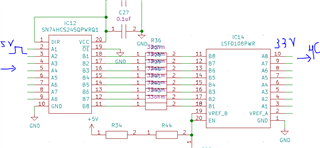
And to receive feedback signal from motor (Feedback signal is PWM signal) I am using SN74HCS245QPWRQ1 > 33ohm damping resistor > LSF0108 > 3.3V GPIO at controller.

So for all three selection (PCF8575 - to send good output signal), LSF0108 (to send good PWM signal on long wires) and SN74HCS245QPWRQ1 (To receive PWM signal) I am looking for some good options.

So far my conclusion is, I need voltage follower op-amp to send good signal and to receive PWM signal (i. e. Low impedance to send the signal and High Impedance to receive the signal).

But I need some good suggestions to pick the right component  for my design. I have 10 of these motors talking to my controller continuously so lot of signals.

Some noise immunity tips would be helpful as well.

  • The LSF does not buffer the signals (it is a passive switch), and works best for open-drain signals.

    Op-amps are for analog signals. For digital signals, you can simply use plain logic buffers. To convert from 3.3 V to 5 V, use a buffer with TTL-compatible inputs, such as the SN74AHCT125. To convert from 5 V to 3.3 V, use any buffer with an overvoltage-tolerant input, such as the SN74AHC1G125.

  • Thank you for your reply .

    To convert from 3.3V to 5V, I have to have I2C expander in place first, so PCF8575 is able to give me 5V output at all port pins. Now as you mentioned I will need a buffer then similar to SN74AHCT125 can I use any 8 bit buffer? so I can have less components and can accomodate more signals in one IC?
    Do you think SN74HCS245-Q1 can do?

    To convert from 5V to 3.3V, first I was using SN74HCS245-Q1 to clear the waveform following with 33ohm resistor and LSF0108. Do you think I need to change anything here?

    If above mentioned IC is not the right choice then please provide some recommendation that I can use with 8 bit channel.

  • Hi Jigar,

    The SN74HCS245 has positive input clamp diodes, which will allow you to down-translate with that device, but only if you have a series resistor at each input (to limit current through the clamp diode). You would just power the 'HCS245 from 3.3V, and add series resistors at each input to limit current. 1kohm is usually sufficient.

    This video shows how that works: https://training.ti.com/zh-tw/clamp-diodes-and-cmos-logic-devices?context=1139265-1148876 

    The video shows this circuit as an example for down-translation using a device with input clamp diodes.

    As Clemens said, you could also use any device that has over-voltage tolerant inputs (ie does _not_ have the positive clamp diode at the input).  One example I could recommend would be the SN74LVC244. You just power the 'LVC244 from 3.3V, and the inputs can be up to 5.5V.

  • Thank you 

    That helped a lot. That clears me for taking in the input signal from 5V PWM to 3.3V.

    Any suggestion on what should be best option for converting from 3.3V to 5V? Because my main issue is sending PWM signal to motors is causing the signals to be clamp but not on receiving them. So may be a buffer that can drive the load should do here. I am not sure which specific though.

    Additionally, Motor side (Integrated Motor Driver) electronics, can accept 5V to 24V signals. So I assume they are not causing this positive clamp, it might be that LSF0108 (as per current circuit) is not able to drive the signal.

  • Hey Jigar,

    Glad I could be of help.

    There are really two good methods of converting a unidirectional logic signal from 3.3V to 5V that I know of.

    The first is what Clemens recommended - and it's certainly an easy and good solution. You can use any TTL-compatible CMOS device powered from 5V and it will take in 3.3V signals and convert them to 5V signals. The one drawback with this approach is that it generally is more power consuming than using a dual supply voltage translator.

    Here's a list of our TTL-compatible input 8-channel buffers that might work for you: https://www.ti.com/logic-voltage-translation/buffers-drivers-transceivers/noninverting/products.html#p480=8;8&p776=TTL-Compatible%20CMOS&p1498=Catalog 

    You could also use a TTL-compatible input transceiver -- generally the pinout on these is a bit easier to work with if you're sending 8 channels in the same direction. Here's a list of transceivers that might work: https://www.ti.com/logic-voltage-translation/buffers-drivers-transceivers/general-purpose/products.html#p1498=Catalog 

    To help simplify, my first pick would be the SN74AHCT245 if I were to take this approach.

    The other option is to use a dual supply translator such as the SN74LXC8T245. This would actually be my first choice since it is a relatively new translator and has many useful features.

    Here's a list of all of our 8-bit translators that might work: https://www.ti.com/logic-voltage-translation/voltage-translators-level-shifters/direction-controlled/products.html#p848=8;8&p634max=5;5.5 

  • Thank you so much. That pretty much resolved everything. 
    Couple of last questions I will ask before wrapping up. 

    So for now, I was using PCF8575 I2C GPIO expander to get 5V Signal Transmitted to Motor Drive.
    I checked it's datasheet and it is also able to provide 50mA of output current.
    Below is my current circuit:

    Now, my question is, If above circuit can work with SN74LXC8T245 then why not with PCF8575? Why I need additional step there?
    Yes to transmit PWM signal to the motor drive I will be using SN74LXC8T245 now onwards instead of LSF0108 BUT additional to PWM, I have two more state level signals to send as well (Direction and Enable signal). Which will be just logic high or logic low.
    I was leaning on PCF8575 to do the trick here. With 1k pull up I am getting 5V out of it. As soon as I connect motor connector Enable signal and Direction signal clamped down to 2V only! I am afraid that even if I use SN74LXC8T245, it will do the same!

    So I am looking for reason that what exactly causing this issue to happen?

    Additionally, the PWM signal I am sending to motor drive (from LSF0108) is actually doing better than PCF8575! Please see below:

    I hope by replacing LSF0108 with SN74LXC8T245 will help me getting 0-5V complete PWM signal.

  • Hi Jigar,

    Now, my question is, If above circuit can work with SN74LXC8T245 then why not with PCF8575? Why I need additional step there?

    I'm not an expert on the PCF8575, but it looks like it's an open-drain device, so it has no positive drive strength. In this case, your 1kohm resistor is all that's holding the line up to 5V, so when it tries to drive "high," basically it's just connecting that 1k pull-up to the load.

    The LXC translator has push-pull outputs, so it can drive current in the low and high states.

    Have you considered switching to a shift register instead of an I2C I/O expander? if you only need additional outputs, you could use an SN74HCS595 or similar device to add 8 outputs and a time and they are very simple to control.

    We have a motor control example using shift registers here: https://www.ti.com/tool/TIDA-01329 

  • Thank you for that. Shift register would be ideal but here my control signals are from 3.3V and for Shift registers they expect control signals and output voltage both as function of Vcc. So I can't use that I think. But that is really a good option.May be I can use LSF0108 to provide those control signals to level shifters at 5V.

  • If I like to use Shift registers then because they are capable of sourcing enough current, do you think 1k pull up is good enough? 5mA from pull up and around 7mA from Shift register can be drawn. Also it has capacity of sinking more than 5mA of current when it is level low.

  • A 1k pull-up won't drive 5mA -- it will only create that much current if it has dropped 5V across it, so that means the output voltage is 0V.

    The get any reasonable drive strength, generally you're going to need a pull-up of about 50 ohms or less, and that isn't feasible -- which is why there are push-pull output devices. The HCS push-pull outputs will drive with about 25 ohms of drive strength on both sides (there's a plot of output resistance in the datasheet's Typical Characteristics section).

    If you replace the I2C I/O expander with a shift register, then you should no longer need a pull-up resistor because it has push-pull outputs.

    You could choose a shift register that's got TTL-compatible inputs, which would allow you to have a 3.3V input and 5V outputs. For example, SN74AHCT595 would be a good choice.

    I recently released a series of videos that goes into detail on how different types of logic inputs work and what all the specs mean located here: https://training.ti.com/node/1139265 

    I also have a detailed series on how the LSF translators work here: https://training.ti.com/node/1139264?context=1139264 

  • Hey Jigar,

    This list is filtered to show shift registers with TTL-compatible inputs:

    https://www.ti.com/logic-voltage-translation/flip-flops-latches-registers/shift-registers/products.html#p1143=Serial-in,%20Parallel-out&p848=8;8&p776=TTL-Compatible%20CMOS&p116=3-State&sort=p1130;asc

    -

    Your filter had only included devices with Push-Pull outputs, but the '595 function is listed as a 3-State output, which is just a Push-Pull output that can also be put into the High-Impedance state.