This thread has been locked.

If you have a related question, please click the "Ask a related question" button in the top right corner. The newly created question will be automatically linked to this question.

TXS0108E: The outputting signal of TXS0108 is bad.

Part Number: TXS0108E
Other Parts Discussed in Thread: TXB0108, TMS320C6678, TXU0104, SN74AXC8T245, SN74AXC4T774, TXU0204

Dear engineers:

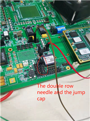
I designed a board that is based on TMS320C6678. The 6678 chip should communicate with another IMU module through the SPI interface. However, the voltage level of 6678 is 1.8V while that of the IMU module is 3.3V. I used TXS0108 to transfer the voltage. When 6678 generates the SPI clock of 1.8V, the corresponding output signal of 3.3V had bad quality.  I disconnected the output of TXS0108 and the IMU module, and I found this operation cannot help the chip improve its output. I also changed another TXS0108 which does not help, either. Somebody suggested that TXB0108 is more suitable for the SPI interface. So I changed the TXS0108 to a TXB0108. Unfortunately, The TXB0108 does not work at all!. The output is a puzzling sinusoidal signal of 41MHz. It made me crazy. Please help me. 

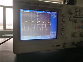
Figure 1: The input signal: a 1.8V SPI clock.

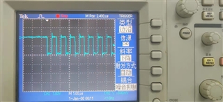
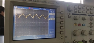
Figure 2: The output signal: a 3.3V SPI clock.

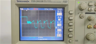
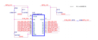
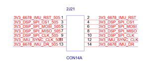
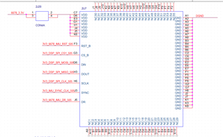
Figure 3: The schematic

  • Hi Zun,

    Most of the issues faced with these device stems from  improper loading. Due to this, I will need to see everything connected to the I/O. There should be no pull-ups or pull-downs on the line. Is it just the CLK line having issues?

     Is there a specific reason to why the scope signal is inverted?

  • hello Dylan. 

    (1) I make sure there are no pull-ups or pull-downs on the signal line. All the signal lines have the same issues.

    (2) The 3.3V signals (the outputs of TXS0108) are connected to a "double row needle." I can use four jump caps to connect the corresponding pins so that the outputs of TXS0108 can connect to the IMU module. This is to say I can disconnect the output of TXS0108 with the IMU module if I do not use any jump caps.

    The schematic is as Figure 1 shows.

    Figure 1: The schematic of the double row needle.

    Figure 2: the double row needle and the jump caps

    (3)  The clock signal is inverted because we set the corresponding mode of the TMS320C6678. I guess the polarity of the signal will not influence the performance of the TXS0108?

  • And what is connected at the other side of the jumpers? How long are the traces?

    The inversion does not matter.

  • The other side of the jumpers is connected to an IMU module called ADIS16505. Now I take the jumpers away so the output of the TXS0108 does not connect to the IMU module. 

    Figure1: The ADIS16505 schematic

    The length of the trace between the pin of the 6678 and the corresponding 1.8V input of the TXS0108 is about 3cm. The length of the trace between the 3.3V output of the TXS0108 and the jumper is about  8cm. However, the signal is still bad when I put my probe of oscilloscope on the output pin of TXS0108

  • Hey Zun,

    Can you provide the scope capture of the input signal and output signal when the 3.3 V side is open connection?

  • Hey Dylan

    Thanks for your reply.

    The Figure 1 and Figure 2 in my major post are the scope capture of the input signal and output signal when the 3.3 V side is open connection

  • Hey Zun,

    You may need to add some series resistors to the 3.3 V side outputs to dampen the ringing.

  • Hello Dylan

    Thanks for your reply. Could you please tell me how to calculate the value of the resistors? 

  • Hey Zun,

    With hardware already built, its better just to test a few options. I would start with 33 ohms and then if that doesn't dampen the ringing enough, move to 50 ohms and try that. These values should be sufficient.

  • Hey Dylan

    Thanks for your help. I tried to put resistors. It seems that the resistors made the signal more smooth. However, the rising edge is still not steep enough. 

    Figure 1: The signal after I put a resistor

    What is even worse, I connected the jumper to use the IMU module. Then I test the 3.3V signal. I found the high level of the signal is only about 1.2V. I guess the drive ability of TXS0108 is not enough. I see the footprint of the TXB0108 is the same as that of the TXS0108. So I directly changed the TXS0108 to the TXB0108. However, the performance of the TXB0108 is worse. The 3.3V output looks like a puzzling sinusoidal signal which is about 3MHz. 

    Figure 2: The output of the TXB0108

    Could you please give me more help? Thank you.

  • The TXS has edge accelerators, but otherwise is a passive switch without any drive ability.
    The TXB has edge accelerators, but otherwise has a drive strength of only 20 µA.

    Bidirectional translators do not work when the load is too high. In this application, you should use direction-controlled or unidirectional translators like the SN74AXC8T245, SN74AXC4T774, or TXU0104/TXU0204/TCU0304.

  • Hey Clemens.

    I think 20uA is enough as the datasheet of my IMU module said the max of the Ioh is 10uA. The problem is that the TXB0108 cannot work as the figure shows.

  • The TXS/TXB also have a limit on the capacitive load (about 70 pF). It appears your load is much larger. (I don't know whether it's caused by long traces, the jumpers, and/or the module.)

  • Hey Clemens

    I make one of the TXB0108 pins away from the PCB board and test the signal on the pin directly. The phenomenon is the same. 

  • Then it might be caused by the oscilloscope probe, or something connected on the other side.