This thread has been locked.

If you have a related question, please click the "Ask a related question" button in the top right corner. The newly created question will be automatically linked to this question.

CD4010B: Further information for its model

Genius 14959 points
Part Number: CD4010B

Hi Experts,

Good day.

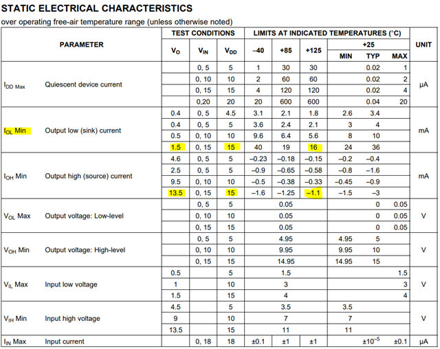
Customer understand that we do not have a simulation model for the CD4010B. However, TI datasheet shows a generic model for this part. It shows diode pullups to the rail for input and output, an Rdson, and on the output a diode pullup from ground to the output pin.

Can we provide anything further on this model, such as the value of Rdson?

Any more information on this model would also be helpful.

Thank you.

Regards,
Archie A.

  • Hi Archie,

    The output impedance can be calculated from the provided datasheet values.

    For example, at 15V, the device is tested for a LOW output voltage (VOL) of 1.5V and the output current of 16mA is measured (in the worst case). This indicates a resistance of VOL/IOL = 93.75 ohms.

    Similarly, when driving HIGH, the output voltage is 13.5V and the current is 1.1mA. This indicates a resistance of (VCC-VOH)/IOH = 1363 ohms.

  • Thanks, Emrys.

    I had one more question about the CD4010. The datasheet states that the absolute maximum for DC input current is +/- 10mA. Does this component have a surge current rating for a given duration?

    Regards,
    Archie A.

  • Hi Archie,

    No, we usually treat the "DC input current" as the instantaneous current limit also. There's no reason to be driving even close to 10mA through the clamp diodes at the input. If you need to sink that kind of current, I'd recommend adding an external clamp diode to handle it.