This thread has been locked.
If you have a related question, please click the "Ask a related question" button in the top right corner. The newly created question will be automatically linked to this question.
Hello e2e team,
I am using the SN74LVC2G17 buffer in my design and connected the PWM inputs as follows via the pull down resistor 10k ohm -->
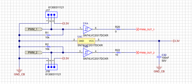
The issue is when I give the supply 3.3V, the pin 2 (of both J17 and J18) both are somehow pulled up (~2.3V) instead of getting tied by GND via pull down resistors. I see the PWM input wave going from 2.3V to 3.3V instead of 0 to 3.3V --> level shift.
Could you please tell me what could be the possible source of error here ? I even tried replacing the 10K resistor value with 1k and 100k but still no change.
Thank you,
Anubha
Does the problem vanish when you disconnect pin 1/3?
Overvoltage (above 6.5 V) could have damaged the inputs. The schematic does not show any ESD protection.
Hi Anubha,
Is this just a schematic or is there a PCB layout?
If you disconnect the PWM input and J17/18, then leave the 10k resistor connected to GND on the input, do you see 0V at the input?
As Clemens asked, does the problem go away when you disconnect pin 1/3?
Regards,
Sebastian