Hi Team,
I am looking to use the SN74LVC1G11-EP as a driver for a PWM DAC and am wondering if there is any additional info on the voltage drop and rise above ground when the part is sourcing and sinking current respectively.
I want to use those to ensure I will get sufficiently low error on the output voltage after an RC filter.
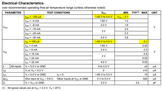
The datasheet has a few currents where the Voh and Vol parameters are given but more detail in the 10uA to 1mA range would be useful.
There is also some amount of cancelling out of the two offsets, especially near 50% duty cycle but I am unsure how much affect that will actually have on the output.
I have also run a sim in Tina TI with the part and seem to get voltages accurate to ~1mV instead of the 100mV listed in the datasheet with a 100uA current draw. I assume the model for the part is not set up for worst case ranges though so it would not be a good representation of worst case values.
Thanks,
Caleb Olson