This thread has been locked.
If you have a related question, please click the "Ask a related question" button in the top right corner. The newly created question will be automatically linked to this question.
Hello All,
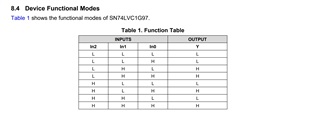
Looking at the datasheet and then looking at the truth table and Figure 5, for instance - I don't see those matching.
How is the logic and truth table supposed to be reconciled?
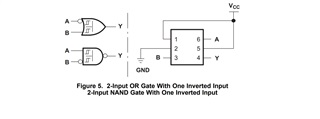
For figure 5 - for the top example - isn't Y = (A)' + B ? In the truth table - using the top row - it says Y = 0, but following the boolean equation, Y = 1.
So, how to determine which one is correct?
Thanks In Advance,
John W.
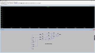
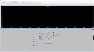
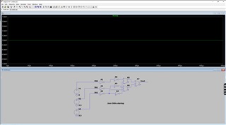
TI - disregard. I was looking at my schematic where I had tied IN1 to GND vs. pulling it high - and was looking at the truth table after that... oops. (Pin 1 tied low vs. pulled high....)
I guess I implemented the unobtainium gate. Ha!
Hey John,
Thanks for the post - and I'm glad you figured it out.
Come back any time :)
Emrys,
Sure thing. These configurable logic gate parts are pretty cool. And propagation delays are either close enough or less than trying to string some gates together.
Best Regards,
John
Hello Again TI,
Is there any errata against this datasheet and/or P/N: SN74LVC1G97 ?
Can Figure 5 - a 2-Input OR Gate with one inverted input be implemented?
Thanks,
John
Hey John,
Is there any errata against this datasheet and/or P/N: SN74LVC1G97 ?
I don't see any unimplemented errors in our internal tracking system.
Emrys,
OK - thanks for checking. We just wanted to make double-sure here.
Best Regards,
John