This thread has been locked.

If you have a related question, please click the "Ask a related question" button in the top right corner. The newly created question will be automatically linked to this question.

CD74HCT11: seek help for chip failure analysis : single channel‘s output of the chip fall below Vcc when its input is high

Part Number: CD74HCT11
Other Parts Discussed in Thread: UCC27531, UCC27524, SN74ACT11

Hi,

      I faced a problem with a new pasted PCBA. The schematic is as below:

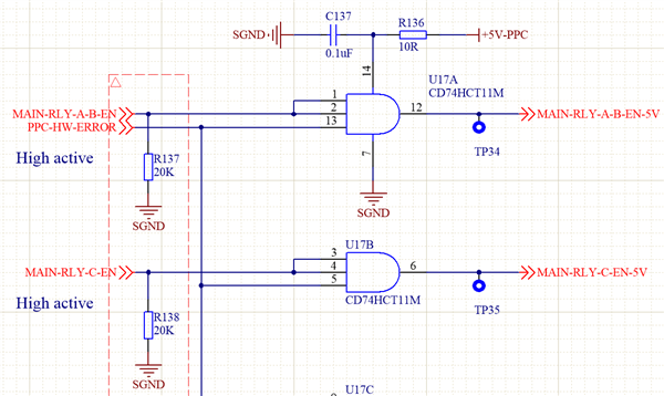
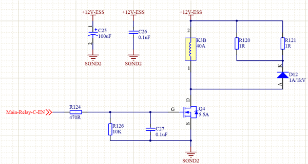
the chip U17 is used to control a MOSFETs Q4 which drive a relay K3。I found it in test that when MAIN-RLY-C-EN signal turn to high level(3.3V),the output MAIN-RLY-C-EN-5V(pin6) rised up to about 3.07V rather than 5V, at the same time the Voltage on pin 14(Vcc, after R136) fall from 5V down to 4.74V. 

It seems like broken but I don't get the reason, the chip could handle 25mA continues output current so I don't think it fails for over current, please help me to analysis the failure reason, thanks!

  • The HC logic family is designed for loads up to 4 mA. VOH is specified in the electrical characteristics table; with a 4 mA load, the output voltage might drop to 3.7 V. For larger loads, the behaviour is not guaranteed. The absolute maximum ratings guarantee only that the device will not get damaged.

    When the MOSFET's gate and C27 are initially discharged, the current is limited only by R124, i.e., you are drawing about 10 mA. But once the gate and C27 are charged, the current is smaller (about 0.5 mA), and the output voltage will be near VCC. So the initial voltage is not necessarily a problem.

    If you do want a pin-to-pin replacement with higher drive strength, use the SN74ACT11. Alternatively, use gate drivers like the UCC27531 or UCC27524.

    What is the purpose of C27? That gate already has a high capacitance.

    The decoupling capacitance should be large enough to handle all current spikes. Add about 10 µF in parallel with C137.

  • Hi, 

             Thanks for reply.  I removed R124 to test the chip itself,but the output is still 3.07V, so I tnink is the chip failure problem. for there is a long trace from chip U17 to Q4, the C27 is used to add a delay time and form a RC filter.  Could it be the problem of U17 failure?

  • Removing R124 increases the current to a potentially damaging level.

    With R124, there is no failure, and a voltage drop is to be expected, as explained in my previous answer.

  • sorry for misunderstanding, removing R124 does not mean short the singal to the mosfets,  I just left pin 6 open and test, there is no any load at that time

  • All outputs share the power supply. Is there anything connected to the others? But a working output without load should not drop below VCC.