Other Parts Discussed in Thread: LSF0108
Dear experts,
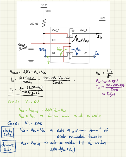
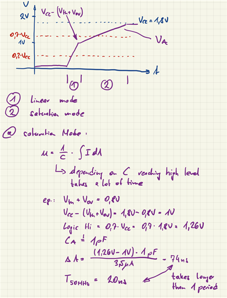
we are using LSF0108-Q1 as levelshifter between 3V3 (uP) and 1V8 (WiFi IC). CLK frequency is about 50MHz.
In our design (at the moment) 47k pull up resistors are used. Signal speed ist 50MHz. In my opinion this should not be working / is not a robust design.
But in lab we see operation and I'm wondering why we have on A side a logic signal.
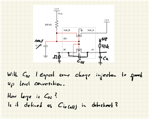
An idea is, that capacitive coupling between port B and A is high and we have some charge injection.
So i wanted to ask, is this the capacitance from B to A when B side (higher voltage) has a logical high and cascode transistor of LSF0108 is turend off? 
Thanks,
Martin