This thread has been locked.
If you have a related question, please click the "Ask a related question" button in the top right corner. The newly created question will be automatically linked to this question.
Hi,
Will this dip/step at the edge be concern? I think the time is short and should not cause an additional pulse and influence the following device.
Could you help confirm?
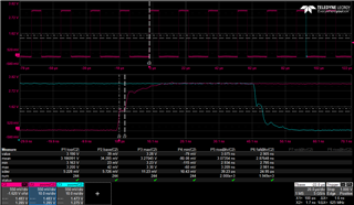
This is a violation of the Δt/Δv limit (which is missing from the SN74LVC244A datasheet, but it still exists), and it is near VCC/2, where it can actually lead to oscillations at the output.
The trace to the input should be properly terminated; see p. 47 of the LVC Designer's Guide.
Thanks, Clemens.
But I need to ask if any TI colleague could provide the missing part for me, since my customer is asking me to explain the reason inside the chip.
This is a violation of the Δt/Δv limit (which is missing from the SN74LVC244A datasheet, but it still exists), and it is near VCC/2, where it can actually lead to oscillations at the output.
Hi Zach,
I would refer to the app note linked below:
https://www.ti.com/lit/wp/slla364a/slla364a.pdf
The typical rise time minimum will be 10ns/V for LVC family.
Hi Albert.
To confirm, should the Δt/Δv limit be followed at everywhere of the edge or just the total Δt/Δv needs to be complied?
From customer plot, the total Δt/Δv is OK. And the dip/step lasts for very short time. Should that be an issue?
Thanks,
Zach
In theory, the Δt/Δv limit applies to all points of the edge. In practice, you need to care only near the actual switching threshold, which is near VCC/2, but that is where the problem actually happens.
You do need to properly terminate the traces (simplest and cheapest is source termination), or use a device with Schmitt-trigger inputs.