Other Parts Discussed in Thread: CD4093B, CD4044B, TL7733B, TPS3710, TL7700-SEP
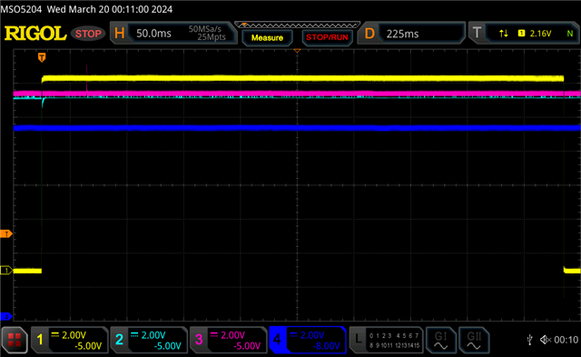
Attached, is our circuit; a well-known RS Flip-flop configured from two of the NAND gates within a CD4093B. for some unknown reason (and luckily), it always come up in the desired state (nQ is high) whenever power is applied. However, I want to make sure that the output ALWAYS comes up in that state. So far, they have, but I do not know why.
What I thought I could do is delay the rise of the nR input to cause its respective output (nQ) to go high.
To achieve this in the breadboard circuit, I added a resistor (R13) and a capacitor (C12) to the pull-up of that input (see schematic in attached zip file). Doing so causes the entire circuit not to work. If I take those out of the circuit, it then returns to desired function. However, in the LTSpice model (forgive me! the circuit preforms as desired. That is why I don't always trust simulations. I’m puzzled. I am looking at the other parts of the circuit to see if they have an impact on the flip-flop, but so far, I have found nothing.
I have included both a PDF and the model of the circuit (with needed sub-circuits) in the attached file, should you wish to see how it works. What, if anything, can I do to ensure that the circuit comes up EVERY TIME in the desired state (see below)? This issue has now become urgent. So, anything you can offer would be very much appreciated. Thank you very much! W. Probasco, 908-246-3873


