This thread has been locked.

If you have a related question, please click the "Ask a related question" button in the top right corner. The newly created question will be automatically linked to this question.

CD4541B: Timer Period setup

Part Number: CD4541B

Hello,

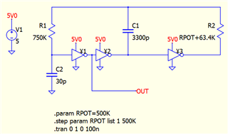
For a while now we have had a product that uses two CD4541 to set a clock period and pulse width.  This is an old product that is predominately on through hole technology and I am currently updating it to surface mount.  My surface mount conversion mostly worked flawlessly except the timing of the circuit seems to have drifted higher.  In the part of the circuit that sets the period I am using Ctc = 3300pF and Rtc = 63.4kohms (with a 500k pot in series to allow adjusting of the period) and Rs = 750kohms; this has set the max Period to 480ms for years, but now it's between 505ms-520ms.  Checking the math this doesn't work out quite right.  2.3 * 63.4kohms * 3300pF = 481us...not milliseconds. I suspect I am just not understanding how to calculate this properly as it's off by exactly a factor of 1000.  I suspect there is something to do with the Rs value but I can't figure it out by reading the datasheet.  Can you help me understand the math?

  • Hello,

    The actual math for solving this is pretty complex if you want to account for variations in all the components and not just solve for special cases (like the datasheet does). There's an excellent application report on the topic that is not made by TI here. The equation provided in the datasheet of F = 1/(2.3 * Rtc * Ctc) makes several assumptions, including a frequency between 1kHz and 100 kHz, and Rs ~= 2Rtc, neither of which are true for your circuit.

    A few years back I built a transfer function that included all of the components for this circuit, including things like input hysteresis and parasitics, but it was impractical to use and thus I never published it. Simulating is much faster/easier for initial values, then bench testing gives the final tweaks required.

    Using a simulator (Qspice), I found that the values you provided give a maximum period of approximately 4.16ms with a typical 3-inverter oscillator. Here's the sim setup if you want to replicate:

    I expect an assumption for your circuit is incorrect (for example, the schematic labelled 3300pF when the actual circuit used a larger capacitor in production).

  • Thank you, I went back and looked at our old drawings and it turns out these capacitors we specified to be 2.5% resistors...I was using 10% on this new surface mount design.  I've ordered new caps to come in tomorrow and I will replace them all with 1% caps.

    I expect this will fix the issue as I was able to cherry pick a good cap from the current caps I have and this was much improved.