Tool/software:
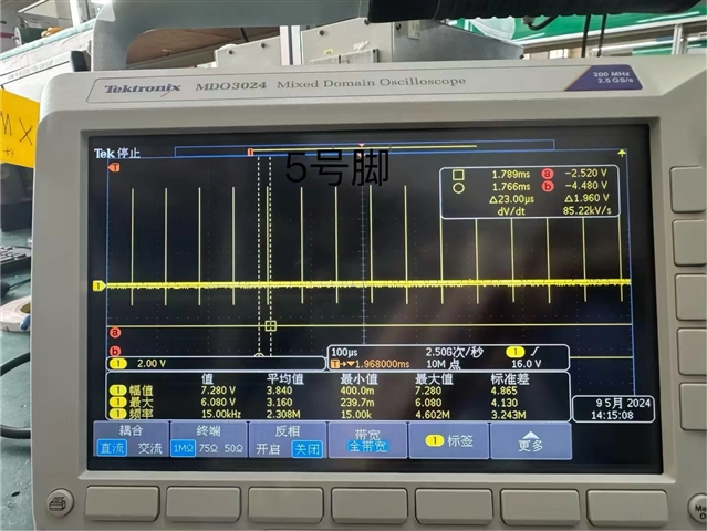
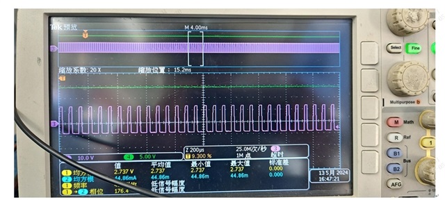
SN74HC74DR,Different batches of chips,they have different waveform.
Why is this?
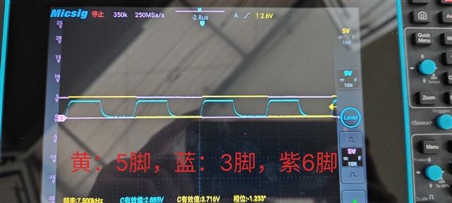
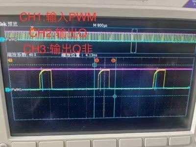
Correct waveform
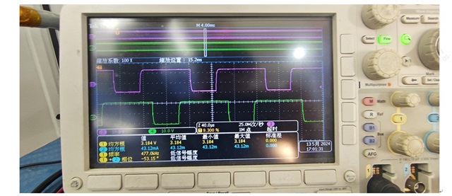
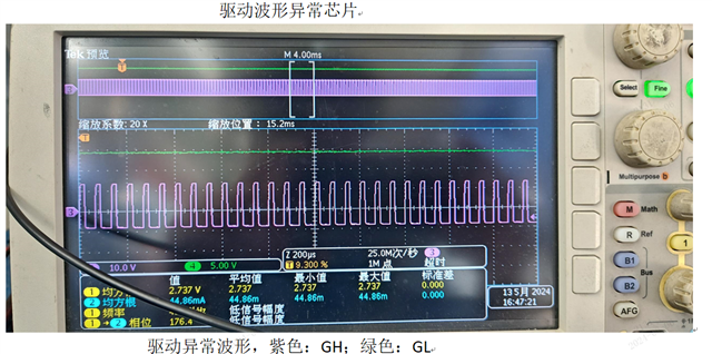
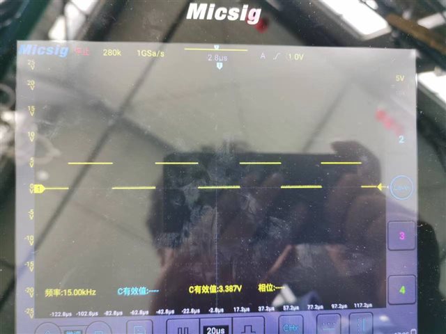
Abnormal waveform
Tool/software:
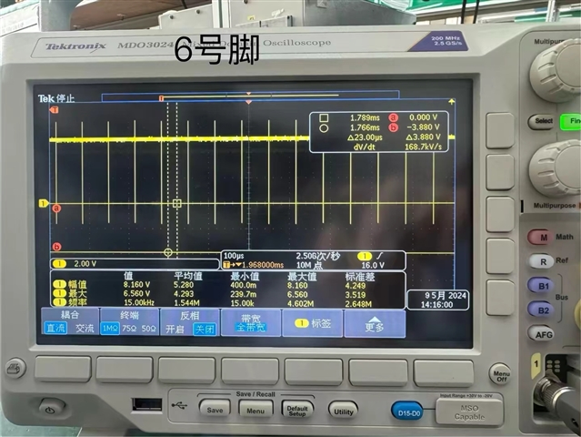
SN74HC74DR,Different batches of chips,they have different waveform.
Why is this?
Correct waveform
Abnormal waveform