This thread has been locked.

If you have a related question, please click the "Ask a related question" button in the top right corner. The newly created question will be automatically linked to this question.

SN74LVC2G17: Do we need dampening resistor at the output?

Part Number: SN74LVC2G17
Other Parts Discussed in Thread: TMAG5111, , SN74HCS541, TSD05, TXU0102

Tool/software:

Hello E2E Community,

We are using SN74LVC2G17 to buffer a sensor output from a remote Open drain TMAG5111 sensor with 0-5V range & a maximum of 5kHz signal speed with 2kHz as typical speed.

Idea is to leverage the Schmitt trigger on this buffer while also creating some level of safety for any EOS event that might occur on the sensor side.

We have incorporated a TVS diode followed by a pulse proof series resistor of 1kOhm before the buffer for safety from the field side cabling. (Any comments on using a higher value resistor here <10kOhm?)

  1. My question is do we need to add series current limiting resistor between the buffer output & the MCU inputs when the trace length is no more than 12mm?
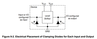
  2. Is there any possibility that the buffer might overdrive the MCU input & cause the damage to the MCU pins?
  3. Can we add a MLCC of 1 to 10nF from Buffer to MCU to slow down the edges of the buffer output & eliminate potential high rise time issues?

Kindly guide.

The PCB is a 2 layer board with solid ground plane & this buffer might be the only component with the high rise time.

  • A resistor between the TVS and the buffer would not protect against positive spikes because LVC inputs do not have clamping diodes to VCC. The TVS alone would be responsible for clamping the voltage to less than 6.5 V. If you want to clamp positive voltages after the resistor, use a different logic family, e.g., SN74HCS541, or add another external diode.

    CMOS inputs have a very high impedance; 10 kΩ would be no problem.

    1. 12 mm is short enough that source termination is not needed. 

    2. No.

    3. Logic outputs can drive a capacitive load of up to about 70 pF directly. Larger capacitors act like a short, can exceed the absolute maximum rating for the output current, and require a current-limiting resistor. An R-C low-pass filter is possible, but would be needed only if you wanted to remove high-frequency noise.

  • Thank you for your inputs ,

    1. On point of series resistor between the buffer output pins & the inputs of the MCU - we do not have to worry about any over current events being driven by the buffer, right? That's the only clarification we are seeking here.

    Any logic family that we can use for 2 channel digital inputs? HCS family has annoying & very odd pin configurations that makes it difficult to route & use on compact 2 layer boards. Hence we chose LVC2G017 as the layout is super simplified & compact.

    Any recommendation for a buffer (single, dual or quad input) that ideally has:

    1. 5V input while working on 3.3V VCC supply
    2. Has Schmitt trigger inputs
    3. Has flow through package pinouts
    4. Has OE ie Enable pin

    I did not find with my filters on the TI Webshop - perhaps you might be better aware of the portfolio than we are.

  • Also, one more clarification on use of ESD protection using TVS diodes - we are using TSD05 that clamps to 7V - 9V maximum - is this acceptable for the ESD/Surge events? Assuming the AMR ratings are DC while the ESD ratings can exceed the AMR DC values.

  • 1. Correct.

    These requirements happen to be matched by a level shifter: the TXU0102 has OE, overvoltage-tolerant Schmitt-trigger inputs, and can be used with both supplies at 3.3 V (but if you have a 5 V supply, use it for the input).

    The absolute maximum ratings must not be exceeded, except for ESD events that are extremely short. Longer surges above 6.5 V can damage the device. (You can add diodes from the inputs to VCC to clamp voltages above VCC. But for 5 V signals, the diode would need to go to a 5 V supply.)

  • Hello ,

    Thanks for the clarification & the inputs!

    I came across this graph in the LVC family in the Maximum Input/Output Voltage section & this graph suggests that the voltages gine beyond 7V approaching ~9V while the AMR for the '245 part is 6.5V only.

    So my doubt is - though TXU0102 makes perfect application use sense here - LVC2G017 is far easier & low cost as it does not need 5V supply to operate as does the TXU0102 needs. Routing 5V signal trace to for TXU series is becoming difficult on our board.

    So having a TSD05 clamp positive inputs at 7V to 9V as these shall be no more than micro second transients - will this be acceptable for the use case? Alternatively can we by any chance use 74HCS family operating at 3.3V VCC while having input signals at 5V?

  • The TXU0102 does not need a 5 V supply; you can use it with both supplies at 3.3 V.

    That graph shows at what voltage the isolation breaks down; this is likely to damage the device. However, even at lower voltages, the isolation can degrade. There are no guarantees for any voltage above 6.5 V.

  • Ohh, nice!

    So to confirm - the TXU0102 will work with when configured with both VccA & VccB = 3.3V while the incoming signals being at A side being 5V & B side ie the MCU side being 3.3V signals?

    If this is the correct interpretation, then this device works out well for our use case.

  • Yes, this will work.

  • Hello ,

    To my surprise the TXU0102 too has no Vcc clamping diodes.

    In this case how does using TXU010x is any different than using 74LVC2G series different?

    Kindly guide updated solution.

  • The '17 does not have an OE input.