Other Parts Discussed in Thread: SN74LVC1G123,
Tool/software:
Hi experts,
I want to know how to handle unused pins.
[Issues]
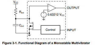
Connect Rext and Cext pins to GND -> abnormal heat generation
* Open Rext and Cext pins -> No abnormal heat generation
[Questions] The data sheet does not describe how to handle unused pins.
Q1. Please let me know how to handle unused pins.
Q2. Why should we do that? Please tell me the reasons clearly.
Best regards,
Hiromu Susami