This thread has been locked.

If you have a related question, please click the "Ask a related question" button in the top right corner. The newly created question will be automatically linked to this question.

SN74AHCT126-Q1: SN74AHCT126-Q1,Effect of overcurrent use on service life

Part Number: SN74AHCT126-Q1

Tool/software:

Hi teams:

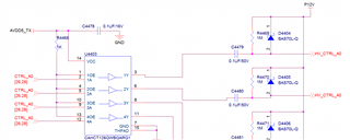
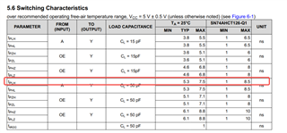
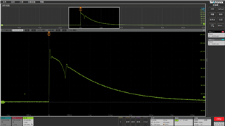
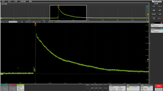
When using the device SN74AHCT126-Q1, there will be a current of 120mA with a pulse width of 1uS when it is powered on. Then when it is working normally, there will be 10 times in 1S with 35mA & pulse width of 1uS. What is the impact on the life of the product?

best wishes!

  • Where exactly does this current flow? Please show the schematic.

  • 1.Output current from the chip side

    2.The schematic is simplified as follows:

  • The schematic does not show the load connected to the outputs.

    Anyway, 120 mA exceeds the absolute maximum rating of 25 mA and can damage the device. You should insert a current-limiting series resistor.

  • Thank you for your reply, we will choose to increase the current resistance. Based on our current current state, can you provide an assessment of the lifetime of the device?

  • The current in the manual is DC current, and it appears as pulse current in our application, whether the device can withstand pulse current better. If it's based on the magnitude and pulse width of our current pulse current, as well as the number of pulses per unit of time, please evaluate the device.here will be a current of 120mA with a pulse width of 1uS when it is powered on. Then when it is working normally, there will be 10 times in 1S with 35mA & pulse width of 1uS. 

  • The datasheet limit is not a DC limit; it must not be exceeded for any amount of time. (And 1 µs is very long.)

    120 mA is likely to degrade or damage the device. The expected lifetime is zero.

  • Hi sir

    Question 1: In order to ensure the life of the IC, is it safe to limit the current to less than 20mA?
    Question 2: We previously encountered a maximum pulse current of 130mA. If the pulse width is controlled at the 200nS level, can the chip be considered safe?
    Question 3: The VOH and VOL voltages in the chip were tested at 50mA, which is greater than the 25mA required by the manual. Does this mean that it is OK to exceed 25mA for a short time?

  • 1. When you stay below the absolute maximum ratings, then the device will not be damaged.

    2. The limit must not be exceeded for any amount of time.

    3. 50 µA = 0.05 mA (but in this case, the absolute maximum rating is for the continuous output current, so you could exceed it for a short time if you ensure that the power dissipation does not become dangerous).

  • Hello Expert,

    The customer's IOUT is a pulse wave not a continue wave. Do you have SOA curve or pulse power consumption wave for them?

    Best regards,

    Wenting 

  • The limit must not be exceeded for any amount of time.

  • Hello Expert,

    We look at the test data of the chip and find that its output waveform edge is 1nS (The minimum time for 50% of the input end and 50% of the output end is 1nS. It can be known that the time for the output voltage waveform from 0 to 90% is less than 1nS.)when the load capacitance is 50pF. According to the calculation, it can be known that the pulse current is 250mA.I=C*du/dt=50pF*5V/1nS=250mA

  • For loads up to about 50 pF, this is indeed allowed. But not for anything larger.

  • When we test the load of 50pF, the output current is 250mA in pulse. Does it mean that the chip can accept 250mA pulse current?

  • It can accept whatever current happens with a 50 pF load. It cannot accept a load of more than 25 mA in any other circumstances.

  • When we test the load of 50pF, the output current is 250mA in pulse.The pulse current under this test condition exceeds the 25mA requirement in your manual. This is a bit contradictory.

  • Hi Gaohuan,

    Any use of our device over our recommended ratings is at the customers risk. TI is not liable for anything outside of the datasheet specs.

    There is not a good way to estimate these affects on a product's lifetime as they are not intended for use at these values to begin with. 

  • Hi team

    The latest manual clearly states that the output can carry a 50pF capacitor, which must have a 250mA current. The limit capacitance parameter provided by the manual has exceeded the current value required by the manual itself, and the manual is contradictory. If we follow the 50pF load in the manual, the current can support 250mA.
    So is the manual wrong, or do we need to believe the value of the 50pF load?

  • The output can support a high current for a very short time. The actual time interval is not specified; what is guaranteed is that it is possible to use a 50 pF load. If your load is higher, the 25 mA limit applies.