- Ask a related questionWhat is a related question?A related question is a question created from another question. When the related question is created, it will be automatically linked to the original question.
Tool/software:
I'm confused by the Input Driver Requirements given in section 8.3.2, and wondering if the 2 mA is required. I hope to interface this chip to an Analog Devices AD7606C-18BSTZ, which has an output drive of around 100 uA.
The TXB0108 datasheet (Revised 2020 page 14) says in the text the drive strength must be +/- 2 mA, but then in the chart it gives a maximum current, equal to V_T / 4 kOhm, where V_T = V_CCI / 2. For the maximum 5.5 V input voltage, that gives me an input current of 688 uA = (5.5 / 2 / 4 kOhm); which is less than 2 mA. Going the other way, if the load is 2 mA, the output voltage would have to be 16 V = (2 mA * 4 kOhm * 2), which is way more than the max output voltage.
1. For my application, V_CCI = 3.3 V, so if I believe the chart, the load is 413 uA in the transition region. Still 4x what ADI wants, but not 20x… am I missing something?
2. If this won't work, is there a TI part which will that has similar pin configuration to the TXB0108DQSR package?
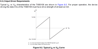
Snip of the text and chart below: