
- Ask a related questionWhat is a related question?A related question is a question created from another question. When the related question is created, it will be automatically linked to the original question.
Tool/software:
Dears,
My customer use our TXB0108. The DSP signal level is 3.3V, and the MVB board signal level is 5V. TI's TXB0108pwr level conversion chip is used for level conversion.
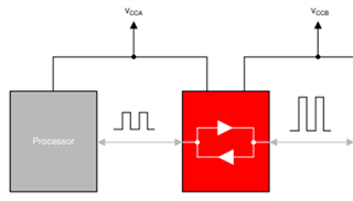
1) The input of TXB0108PWR chip is connected to DSP F28335, and the output pin is left floating. The wiring is as shown below:
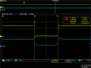
Use an oscilloscope to confirm that the signal level conversion is normal, as shown in the waveform below.
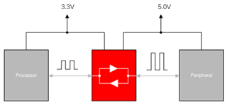
2) Connect any adapter board signal to the MVB board and test the 3.3V signal at the input end and the 5V signal at the output end of the adapter board:
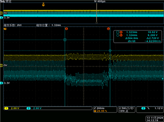
There is a lot of interference between the 3.3V and 5V levels, and the waveform is distorted.
Please help to find the reason, thank you
Best Regards,
Arabella


