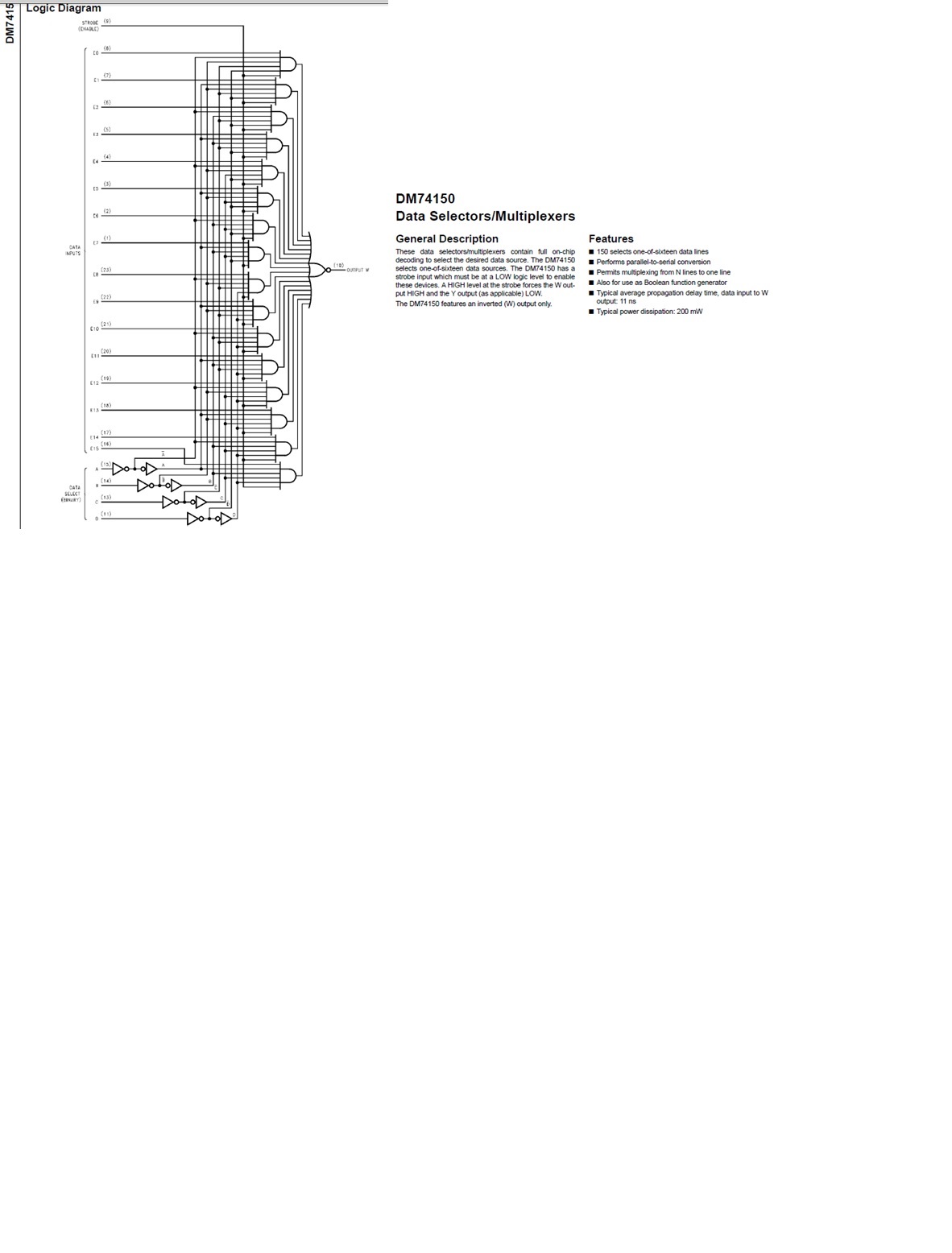
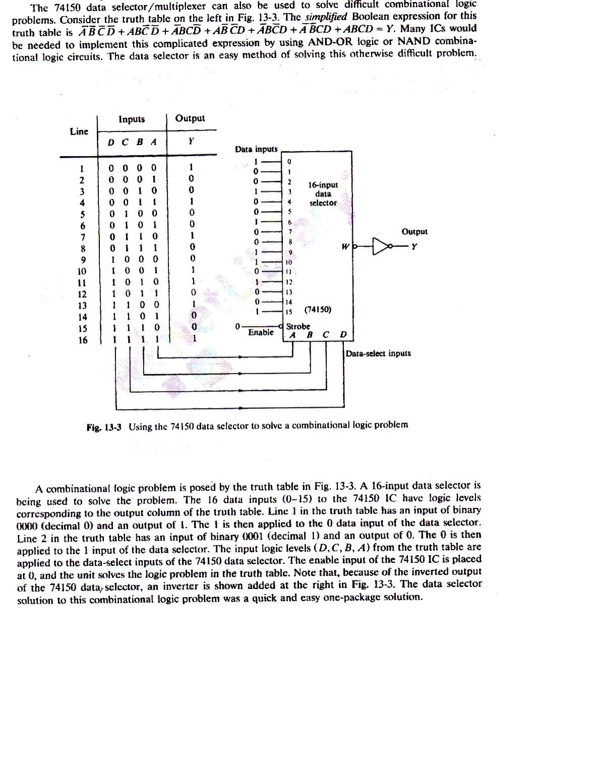
TTL 74150 Data Selector. I figured out how to insert an image.
This thread has been locked.
If you have a related question, please click the "Ask a related question" button in the top right corner. The newly created question will be automatically linked to this question.
Don,
I'm glad you could get the image sorted out. I'm not entirely sure what your question is though. This image shows how to use a 16:1 mux to solve a 4-bit combinational logic problem by basically hard-coding the truth table into the inputs of the mux. The output of the device will be the same as whatever input channel is selected.
Emrys, In your answer you say, "This image shows how to use a 16:1 mux to solve a 4-bit combinational logic problem." How does it solve the problem. The problem is already solved because you are just hard-coding the truth table into the inputs of the mux. The 74150 is just regurgitating what you enter into it.
The other part of the question is this. What does the output from the mux look like. It seems to me it is just a series of ones and zero that match the inputs. If I am correct about the output, how can the demux interpret this series? what am I missing? I think I am basically having problems understanding what the word solve means in this context.
I understand now.
The truth table in your original post is the 'problem' -- many times in logic we just have a series of inputs given to us with associated desired outputs. These can be solved a number of ways -- one traditional method is to develop a Karnaugh map and use that to develop an AND / OR gate network to produce the desired outputs.
Exactly as you said, this solution is just a hard coded truth table. The benefit is that only one part is required to reproduce a possibly very complex logic gate array. The point of this system is to take 4 inputs and generate a previously specified output.
First of all I appreciate your quick response and your patience with me. I understand your answer completely.
The attachment above shows the features for the 74150. One of the features says "also for use as a Boolean function generator". How does the 74150 produce the Boolean function that was given in my original post?
The truth table is generated from the boolean function. If A, B, C, and D are all zero, then the output is HIGH. This is indicated in the boolean function by "A\ B\ C\ D\" (using \ for 'not'). The truth table shows that there are only 7 states that produce a HIGH output, which correspond to the 7 OR'd together components of the boolean function.
So, in essence, the 16:1 mux takes the four inputs for the boolean function as its A, B, C, and D inputs, then 'solves' the boolean function and outputs Y.
Emrys, Thank again for your answer. you say that Y is either a 0 or 1. How do I know what a 0 or 1 means? Is it a stream of 0s and 1s. If so, how do I know what they represent?