This thread has been locked.

If you have a related question, please click the "Ask a related question" button in the top right corner. The newly created question will be automatically linked to this question.

CD4541B - Power up state of Q output and Autoreset with 5V supply

Other Parts Discussed in Thread: CD4541B

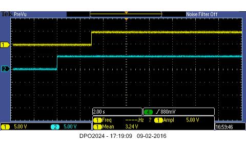
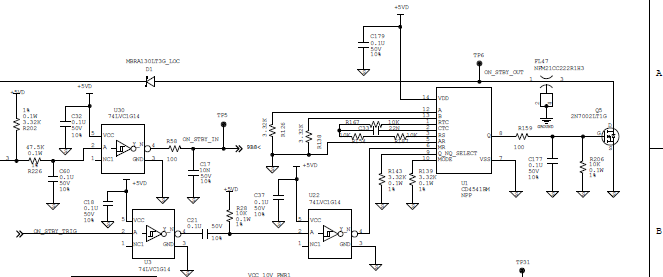
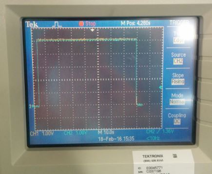
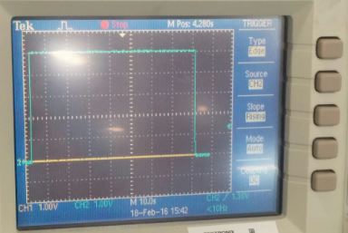
We are using CD4541B to maintain the system ON/OFF state. As per our requirements we need the Q output of the timer should be Logic High at powerup. The MR pin is driven by micro-controller with continuous PWM signal of 200ms ON time and 200ms OFF time. But the micro-controller takes about 300mS to come out of POR and about 100mS to start the continuous PWM signal. 

Currently Q_NQ_SELECT pin (Pin9) is pulled down to Zero. Based on the datasheet if pin 9 is zero, the output Q will be zero at power up. But in our testing we have identified that even with Pin9 pulled down to GND the Q is high at power up.

Why the IC is behaving different from datasheet?

An additional question is, as per the datasheet we are using Autoreset feature of the IC with the input power supply of the IC as 5V. The datasheet recommendation is to use auto reset only if the supply voltage is greater than 5V. What is the side effects if the supply voltage is just 5V that can supply 100mA current.

  • Hi Kiran ,

    The power up initial state of any clocked devices is indeterminate unless a valid input /clock comes in .
    The Vcc needs to be valid under normal operating conditions and the output Q should be zero when pin9 is zero.
    Autoreset should work as long as the supply voltage is within the recommended conditions .
  • Hi Shreyas,

    As I mentioned even with Q_NQ_SEL (Pin 9) configured as zero the output Q (Pin8) is low at power up, but after 2 sec it becomes high without any trigger on MR pin.

    If Pin9 is pulled high, the exact opposite happens. The output Q goes high at power up but after 2 sec it goes low.

    The behavior is not matching the truth table in page 2 of datasheet.

    I'm unable to attach the pictures along with the post. How to share the waveforms?

    Also what should be the state of the pins 9 and pin 5 at power up to ensure the output Q will be zero till a trigger is applied on MR pin?

    -Kiran
  • Hi Kiran ,

    I have attached an app note explaining the initial state on power up for the clocked devices . During power up , the Q and Q/ would be complimentary but not determinate . Once the power up is done and with valid clock or input , the outputs can be determined .powerup_clockeddevices_scha005a.pdf

  • Hello Shreyas,

    I'm looking for exact answer on What is the power up state of Pin 8 on the CD4541B with Pin 9 is pulled down or pulled up?

    Based on the measurements here is what is observed and I'm not sure if this completely conforms to datasheet. I appreciate if you can clarify the below behavior.

    Pin9=0, After power up Q will stay low (2 or 3.5 sec) and goes high and stay high continuously.

    Pin9=1, After power up Q will stay high (2 or 3.5 sec) and goes low and stay low continuously.

    -Kiran

  • Hi Kiran ,

    Thank you for the scopeshots . What do yellow and blue represent ?
    The datasheet mentions that initial low after reset , but does not indicate this being in power up state . Reset state is different from power up . After powering up the device and then enabling the MR (or Autoreset) pin with Pin9 0 / 1 , does Q follow the truth table ?
    What is the state of MR pin when power up?Being an input pin it shouldn't be floating ,which may pick up random signal level triggering the output.
    I have also placed order for samples to verify in our lab here meanwhile.
  • Hi Shreyas,

    Blue trace is power input to IC. Yellow is the output Q.

    From the scope shots, the output Q goes high after 2 to 3.5 sec when Pin9=0, and the output Q goes low after 2 to 3.5 sec when Pin9=1. This means the IC behavior doesn't follow truth table. Also the delay of 2 to 3.5 seconds may be result of Auto Reset. The AR pin is tied to 0 which means auto reset is enabled.

    The MR is stable at zero all the time since there is no trigger signal output from microcontroller as of now.

    -Kiran

  • Hi Kiran ,

    I rigged up the device and here are the scopeshots I have below . The blue is the power rail at 5V and yellow is the Q output .

    Pin5 and Pin 6 = 50 ohms to Gnd . All other pins are open.

    Pin 9 = 5V (connected to Vdd ), timescale 10sec.

    Pin5 and Pin 6 = 50 ohms to Gnd . All other pins are open.

    Pin 9 = Gnd thru 50ohms resistor . Timescale 10sec.

    any conditions on my side which doesn't match your setup ? You think there could be noisy environments around which could have affects on the output ?

  • Hi Shreyas,

    This could be because of not having the timing components RTC, CTC and Rs. Will you able to repeat the experiment by using the components similar to the design I've shared previously.

    -Kiran

  • Hi Kiran ,

    does this mean that without the external components , you were seeing the device behave as per datasheet ?
  • Hi Shreyas,

    I have not performed any test without the timing components. I was mentioning the results were different in your experiment due to not having the timing components.

    I appreciate if you can address our concern on the IC behavior.

    -Kiran

  • hi Kiran ,

    I will try to set it up again in the lab and will share more info with you . It might take a while though since I am involved in new product releases coming up shortly, meanwhile , if you can also see how the device performs with the components removed can be good to compare it against the findings I have here .