This thread has been locked.

If you have a related question, please click the "Ask a related question" button in the top right corner. The newly created question will be automatically linked to this question.

Layout Guidelines for SN74VMEH22501A

Other Parts Discussed in Thread: SN74VMEH22501A, SN74VMEH22501A-EP

Dear Technical Suppot Team,

I have a question about  SN74VMEH22501A.

 Datasheet of SN74VMEH22501A doesn't describe Layout Guidelines.

http://www.tij.co.jp/jp/lit/ds/symlink/sn74vmeh22501a.pdf

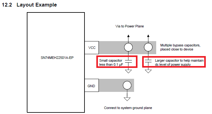
But  Datasheet of SN74VMEH22501A-EP describes  Layout Guidelines on page 30.

http://www.tij.co.jp/jp/lit/ds/symlink/sn74vmeh22501a-ep.pdf

Can I use this for SN74VMEH22501A?


Best Regards,

y.i

  • Hi Y.i ,

    Yes , you can use the same layout guidelines for the commercial part as well.
  • Hi Shreyas,

    Thank you for your reply.

    Layout Guidelines show following about  bypass capacitors .

    ------------

    TI recommends to use multiple bypass capacitors to stabilize the supply line. To reduce high-frequency noise, TI

    recommends a small capacitor (0.1 μF, or less) for every two VCC pins on the VME side of the VMEH22501.

    The capacitors should be as close as possible to the VCC pins. An additional large capacitor close to the chip

    helps maintain the dc level of the power-supply line.

    ------------

    How is the value of larger capacitor?

    Does it being placed for every two VCC pins at least like small capacitor?

    Best Regards,

    y.i

  • Only a single large capacitor is needed. It does not need to be as close to the chip as the small ones.

    Typically, there is only one large capacitor for the entire board, near the power supply. Its value depends on how much power the other components can use continuously, and on how stable the supply is. Often, the power supply's datasheet recommends a certain output capacitor. If you don't know better, just try 10 µF.