This thread has been locked.

If you have a related question, please click the "Ask a related question" button in the top right corner. The newly created question will be automatically linked to this question.

Button Controlled LED Dimmer w/ Counter & Multiplexer??

Other Parts Discussed in Thread: SN74LV161A, SN74LV4051A-Q1, SN74LV4051A, BQ24040

I need to pick some brains and hopefully this forum can help. I'm trying to come up with a circuit that controls dimming of a LED driver without using a MCU, only  one push button. Each push of the button increase the brightness. The LED driver has voltage controlled brightness on the feedback pin or the brightness can be controlled at the enable pin by varying the duty cycle of a PWM signal.

The cost of a MCU is ~$0.30 so the goal is to create something for that cost or less.

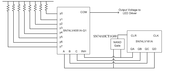
One idea I had was to use a SN74LV161A (4-bit Binary Counter) and have the push button connect to the clock signal. The output of the SN74LV161A would then feed a SN74LV4051A-Q1 (8 channel multiplexor). The input to the multiplexor would be different pull-up resistor values on each pin.

The problem with this circuit is that we need to have the LEDs turn off on one of the button pushes so I'm thinking something like using the RCO fed to an inverter which is connected to the enable pin of the LED driver. The other issue I see is that the multiplexer only has 3 inputs but the counter has 4 outputs. Ideally I would like to have the LED brightness in 7 or 8 steps with one of the steps being LED OFF.

I initially tried coming up with a PWM circuit based on maybe a 555 timer but everything I would come up with cost more than the $0.30 MCU.

  • Hi George,

    I beleive your idea using the SN74LV161A with the SN74LV4051A-Q1 and pull-up resistors should work! I drew up a couple options for you. One gives you an off state and 7 brightness levels and the other gives you an off state with 8 brightness levels.

    The first one uses three of the counters outputs to change the MUX state and one of the counter outputs to drive the CLR pin LOW through an inverter. This way once the counter gets to "1000" the counter will reset to "0000" and the MUX will select y0, which I tied to ground for your off state.

    The second option is essentially the same thing but instead of using one of the MUX inputs as the off state, I utilized the inhibit pin to shut off . All four of the counter outputs are used to drive the MUX selects and inhibit pin. This time I have the QA and QD connected to a NAND gate that will drive the CLR pin LOW once the counter reaches "1001". This way you get an off state with 8 brightness levels.

    The inverter and NAND gate would add maybe a nickel to your cost and keep you under $0.30. Also, is there a reason for using the Q1 version of the SN74LV4051A? You could shave another penny or so using the non-Q1 version.

    What do you think?

    Regards,

    Joe

  • Hi Joe,

    Thanks for looking at this and taking it to the next level! The only part I wonder about is if the LED driver will turn OFF when the feedback pin is pulled to GND. With the enable pin you can use a zero duty cycle to turn it off. When using this analog dimming control on the feedback pin I was thinking of how to pull the enable pin low on one of the states would would have to be a different output pin. The driver I was planning on using was a AP5724. Looking at the spec I think pulling the feedback pin to ground would be a bad thing since the resistor connected between the FB and ground controls the LED current.

    So your idea looks really good to get the 8 steps. Maybe instead of grounding Y0 it's has a very high resistor value? Disabling the part with the enable pin would definitely be better since it would turn it off though. That's why I was thinking of trying to use the RCO pin

    Thanks,

    George

  • Here's a thought. Preload the SN74LV161A with a 1000 input. Then the lower 3 bits of the output would still count from 0 to 8 but I'll get the benefit of having RCO set when it rolls over. Not sure how to pull the LOAD signal low to preset the counter though...
  • George,

    Thank you for sharing the AP5724 datasheet! Now after looking at the LED Driver, I agree that it wouldn't make sense for y0 to be shorted to ground.

    Section 2 on page 9 of the datasheet explains using a DC voltage on the FB pin to control the dimming of LEDs. Based on this description it looks like the larger the DC voltage the less current there will be across the LEDs and therefore the less illuminated they will be. The application example shown on page 9 says that with the resistor set up they have allowed for control of the LED current from 0mA to 20mA. This means you should be able to completely turn the LEDs off using this method, and can adjust the resistor divider to allow for more current.

    Instead of y0 tied to ground, you could tie to VCC and then add the resistor divider as shown in figure 3 of page 9 in the datasheet to set your LED current range.

    Thoughts?

    -Joe
  • Hi Joe,

    I really didn't want to use a Diodes LED driver but I couldn't find a TI one that competes on a cost basis. I did read that bit on page 9 but I missed the 0mA current at higher voltage levels. The only issue I can see with this is that the Quiescent Current is 500uA vs a Shutdown Current of 0.1uA. Since this is a battery operated product (at least I'll be able use the TI BQ24040 Charger in this design!) the best case would be somehow use the enable pin to turn the driver off.

    On page 2 of the SN74LV161A datasheet it says "Enabling RCO produces a high-level pulse while the count is maximum (9 or 15 with QA high).". I'm not quite sure if RCO really does go high on 9 but I think that's a statement for a different part?

    I think if I was able to use your circuit idea and have the RCO signal control the enable pin of the LED driver then the perfect solution is created.

    Your turn...

    -George
  • George,

    Based off of the logic diagram on page 3 of the SN74LV161A datasheet and the timing diagram on page 5, I would agree with you that RCO produces a high-level pulse only when the count is at 15. For this to work QA should be pre-loaded 'HIGH'.

    I will think on this.

    -Joe
  • Joe,

    I'm thinking that perhaps the statement "Enabling RCO produces a high-level pulse while the count is maximum (9 or 15 with QA high)." is boilerplate text copied from somewhere but there should be some part that does toggle RCO when the count is 9 and that's the mystery part I need!

    George 

  • Hi Joe,

    I wired up on of the SN74LV161A parts and it only does set RCO when the count hits 15 so I'm a bit puzzled by the 9 or 15 comment in the datasheet.

    I started looking at other parts and I think the CD4024BE might be a better part. I say that because it has schmitt trigger inputs which would help with using a tactile switch to generate the clock pulses and it has a reset input signal that can be directly fed from Qd output.

    I came up with an idea to use the outputs to feed into a 3-input AND and use that to generate the enable signal for the LED driver.

    I just through together a quick circuit which I think might actually work.

    Take a look and let me know what you think.

    ThanksLED Dimmer Circuit.pdf,

    George

  • Hi George,

    The logic looks good and makes sense. My only concern is that the enable signal to the LED driver is only high when Q1, Q2, and Q3 are HIGH. It looks like the enable signal should be HIGH until you want to turn off the Driver. So maybe instead of the AND gate, connect Q4 to the enable pin through an inverter. This way when Q4 goes high, enable goes LOW to turn off the driver and RESET is HIGH waiting for the next clock pulse to set Q1-4 to '0000'.

    Thoughts?

    -Joe
  • Hi Joe,

    Thanks, good catch on the enable net logic. I had trouble using a push button switch for the clock signal on the SN74LV161A. For some reason my RC circuit wasn't enough to remove all the glitches so the circuit was getting a lot of false clock pulses. I'm hoping that the CD4024BE with it's Schmitt trigger inputs will help eliminate any false clock signals. I think I've got everything to wire up a test case on this and prove it out so I'll let you know how it goes.

    Thanks,

    George

  • Hi Joe,

    I remember now why I was looking at using the output to control the enable pin of the LED driver. If you have Q4 connected to the reset pin of the CD4024BE the device will immediately reset without waiting for a clock pulse. If I change to a 3-input NAND that solves applying the correct enable signal to the LED driver (high for enable low to disable). Since reset occurs independently of the clock I would need some way to hold the system in this state but wait for the next button push to reset the counter. 


    Such a simple concept but I haven't found the correct way to do this yet and it's bugging me!

    Thanks,

    George

  • George,

    Good catch, I overlooked that reset is independant of the clock.

    I agree that the NAND gate on Q1-3 will serve the same purpose as the inverter on Q4. Unfortunately this reduces the number of brightness levels you can achieve by one because you will no longer utilize Y7, since the driver enable is LOW.

    That being said, it sounds like you have your solution. When Q1-3 are HIGH, driver enable goes LOW and you have your off state. With Q4 tied to reset, on your next clock pulse reset will be triggered and the enable will go HIGH. Unless you are saying you tried this and it didn't work..

    -Joe